
VOLVO 14743661 EC900/EC950 Track Guide Wheel/Front Idler Assembly-Heavy-duty crawler track undercarriage components manufacturer&supplier


Technical Specification: Guide Wheel / Track Front Idler Wheel Assembly
Part Identification:
- Compatible Machine Models: VOLVO EC900, EC950 Crawler Excavators.
- Application: Undercarriage System, Front Guidance and Tensioning.
- Component Aliases: Front Idler, Guide Idler, Track Idler.
1.0 Component Overview
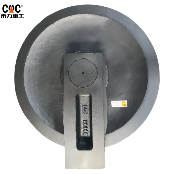
The Guide Wheel / Track Front Idler Wheel Assembly is a critical, non-driven component located at the forward end of the excavator’s undercarriage frame, directly opposite the drive sprocket. It serves as the primary forward guide and the main interface for track tension adjustment. This assembly is engineered to withstand significant impact loads, constant abrasive wear, and substantial lateral forces, making it a vital element for stable and efficient machine travel.
2.0 Primary Function & Operational Context
The core engineering functions of this assembly are:
- Track Guidance and Path Definition: As the name “Guide Wheel” implies, it acts as the forward directional pivot point for the track chain, reversing its path after ground contact and guiding it smoothly back towards the drive sprocket, thus defining the track’s loop.
- Track Tension Adjustment Mechanism: The idler is mounted on a robust sliding mechanism that allows it to be moved forward or backward. This movement is controlled by a hydraulic or grease-filled tensioning cylinder, which is used to set the correct track sag—a critical parameter for optimizing performance, power efficiency, and the service life of the entire undercarriage.
- Primary Impact and Shock Absorption: Due to its forward-facing position, the idler is the first component to encounter obstacles like rocks, stumps, and trench walls. It is specifically engineered to absorb and dissipate substantial shock loads, protecting the more structurally integral undercarriage frame and final drives.
- Track Stabilization and Alignment: The wide profile and integrated flanges of the idler wheel work to maintain the lateral alignment of the track chain, preventing derailment during counter-rotation turns (“pivoting”) and operation on slopes.
3.0 Detailed Construction & Key Sub-Components
This assembly is a complex, sealed system designed for extreme-duty applications:
- 3.1 Idler Wheel (Rim): A large-diameter, robust wheel. Its surface is precisely machined and hardened to provide optimal contact with the track chain links and resist wear. In heavy-duty configurations, the rim may be a two-piece design with a renewable wear ring to reduce long-term maintenance costs.
- 3.2 Flanges: Integral lateral guides on both sides of the rim. These flanges are critical for containing the track chain, preventing lateral derailment during side-loading operations. They are built to withstand direct impacts and constant abrasion.
- 3.3 Internal Bearing and Bushing System:
- Shaft: A high-strength, hardened steel stationary shaft that is securely mounted to the idler’s support arms.
- Bearings/Bushings: The idler housing rotates on the shaft via a set of large, heavy-duty tapered roller bearings or bronze bushings, selected for their superior capacity to handle extreme radial loads and occasional axial thrust forces.
- 3.4 Multi-Stage Sealing System: This is the most critical subsystem for service life. It typically consists of a primary radial face seal or multi-lipped seal, a secondary seal, and often a labyrinth-style grease chamber. This multi-barrier approach is essential for effectively excluding fine, abrasive particles (e.g., quarry dust, slurry) and moisture, while retaining the high-performance grease within the bearing cavity.
- 3.5 Mounting Bracket and Sliding Mechanism: The assembly includes a forged or cast bracket with precisely machined sliding surfaces. These surfaces interface with the matching guides on the undercarriage frame and are connected to the push-rod of the track tensioning cylinder, allowing for precise adjustment of the idler’s position.
4.0 Material & Performance Specifications
- Material: High-Carbon Alloy Steel Casting or Forging.
- Hardness: The rim running surface and flanges are through-hardened or induction-hardened to a typical range of 55-62 HRC, providing an optimal balance of high impact resistance and superior abrasion wear properties.
- Lubrication: Pre-filled with a high-temperature, extreme-pressure (EP) grease. Most assemblies feature a standard grease fitting for periodic re-lubrication to help purge the seal chamber of minor contaminants and extend service intervals.
5.0 Failure Modes & Maintenance Considerations
- Wear Limits: Serviceability is determined by measuring the reduction in flange height and rim diameter against VOLVO’s specified maximum wear limits. Worn flanges significantly increase the risk of track derailment.
- Common Failure Modes:
- Flange Spalling and Fracture: Cracking, chipping, or complete breakage of flanges due to high-impact loads from obstacles.
- Rim Grooving and Concave Wear: Abrasive wear from the track chain links forming grooves or a concave profile on the rim, leading to improper track contact and accelerated chain wear.
- Bearing Seizure: A catastrophic failure often precipitated by seal failure, leading to contamination ingress. A seized idler will not rotate, acting as a brake and causing rapid, severe wear to the track chain bushings and the idler itself.
- Sliding Mechanism Seizure: Corrosion, damage, or contamination of the sliding brackets can prevent tension adjustment, locking the idler in place and compromising track performance.
- Maintenance Practice: Regular inspection for free rotation, structural integrity, and audible/visible signs of bearing failure is essential. Track tension must be checked and adjusted strictly according to the manufacturer’s operational manual. Crucially, the idler should be replaced in conjunction with the track chain and other undercarriage components to prevent accelerated, mismatched wear.
6.0 Conclusion
The VOLVO EC900/EC950 Guide Wheel / Track Front Idler Wheel Assembly is a fundamental and high-stress component critical for the stability, mobility, and longevity of the excavator’s undercarriage system. Its dual role in guidance and tensioning makes it indispensable for proper machine function. Proactive monitoring, correct tensioning procedures, and system-synchronized replacement are essential maintenance disciplines. Using genuine or certified OEM-equivalent parts ensures the required dimensional accuracy, material properties, and sealing performance to withstand the severe operating conditions expected of large-scale excavators, thereby protecting the significant investment in the equipment.
Products categories
-
Idler Wheel Dh180/Dh220 Daewoo Excavator Idler ...
-
Doosan Mini Excavator Front Idler/Idler Roller/...
-

XCMG Part#414101964 XE700 Tension Wheel/Front I...
-
pc55 idler wheel and track adjuster pc200 track...
-

LIEBHERR 10004544 10009659 5614992 R934 Track F...
-

Hyundai (P/N:81ND-13050) R800-FRONT idler assem...


