
SANY SY1250H SSY004621574 Track Sprocket Wheel Assembly / Heavy duty EXC undercarriage Parts manufacturing expert // CQC TRACK // OEM manufacturer and Source factory


Technical White Paper
SANY SY1250H SSY004621574 Track Sprocket Wheel Assembly: Heavy Duty EXC Undercarriage Parts Manufacturing Expert — CQC TRACK / OEM Manufacturer and Source Factory
1. Executive Summary: Engineering the Power Interface
The 120–125 metric ton hydraulic excavator class represents the pinnacle of mass excavation capability in mining and heavy construction. Machines of this scale operate at the very limit of conventional hydraulic excavator design, where every undercarriage component must withstand forces that would rapidly destroy standard-duty equivalents. The SANY SY1250H stands as a flagship model in the 120-ton mining excavator segment, and its Track Sprocket Wheel Assembly (OEM Part Number SSY004621574) serves as the critical interface where final drive torque meets track propulsion.
This document provides a comprehensive technical exposition of the SANY SY1250H SSY004621574 Track Sprocket Wheel Assembly as manufactured by CQC TRACK (Heli Machinery Manufacturing Co., Ltd.) . Designed as a forged, induction-hardened heavy-duty sprocket—referred to interchangeably in industry terminology as the drive wheel, final drive sprocket, track sprocket, or sprocket rim assembly—this component is mission-critical for transferring immense torque from the travel motor to the track chain. Its failure can lead to catastrophic downtime and costly damage to the entire undercarriage system.
What fundamentally distinguishes this product is the combination of advanced manufacturing methodologies and rigorous quality control. Manufactured within an ISO 9001:2015 certified facility, the assembly utilizes closed-die forging techniques rather than casting, employs controlled induction hardening on tooth flanks, and incorporates precision CNC machining on all critical interfaces. The supplier, CQC TRACK, functions as a direct-source manufacturer and factory, eliminating multiple layers of intermediaries while maintaining engineering capability for both OEM and ODM production requirements.
This white paper is structured for procurement professionals, fleet maintenance engineers, mining equipment managers, and global distributors. It progresses from host machine platform analysis and part number identification, then proceeds through exhaustive engineering deconstruction of the sprocket assembly, material science specifications, the critical MTG milling technology, quality assurance frameworks, and concludes with the supply chain advantages inherent in the OEM manufacturer / source factory model.
2. The SANY SY1250H Host Machine: Technical Platform Overview
2.1 Machine Classification and Operational Profile
The SANY SY1250H is a 120-ton-class hydraulic crawler excavator engineered expressly for large-scale mining operations, rock quarrying, heavy infrastructure projects, and mass earthmoving applications. The machine has earned recognition as the “Mine Carrier” within the Chinese heavy equipment industry, winning both the “Golden Finger Award” as part of the TOP50 engineering machinery products and the CMIIC “Mining King” honors, affirming its position as a benchmark for domestically produced large excavators.
The SY1250H is purpose-built for demanding heavy-load conditions in stone, coal, and metal mining operations, with strong heavy-duty operational capability and high reliability as the primary design objectives. Through refined matching control technology, the machine optimizes operational energy consumption to achieve the best possible balance between productivity and efficiency.
SANY has positioned the SY1250H as a strategic product aimed at reducing reliance on imported 100-plus-ton excavators, with multiple proprietary core technology advantages and fully independent intellectual property, including several patents that are domestic industry firsts. The excavator supports more than 20 optional working devices, offering super adaptability across diverse operational requirements.
2.2 Powertrain and Hydraulic System Specifications
The SY1250H is powered by the Cummins QSK23 diesel engine, a heavy-duty 23-liter displacement, six-cylinder, direct-injection, four-stroke, water-cooled, turbocharged powerplant. Key engine parameters include:
| Parameter | Specification |
|---|---|
| Engine Model | Cummins QSK23 |
| Displacement | 23 L |
| Rated Power | 567 kW @ 1,800 rpm |
| Maximum Torque | 3,468 N·m @ 1,350 rpm |
| Fuel Tank Capacity | 1,560 L |
| Hydraulic Tank Capacity | 830–1,100 L |
The engine delivers robust power with ample reserve capacity, achieving high dynamic response, low fuel consumption, and proven reliability. The rated operating power of 567 kW places the SY1250H firmly in the ultra-large excavator category with a horsepower output exceeding 760 HP.
The hydraulic system employs a fully electronically controlled closed-center large-flow hydraulic main valve combined with a four-pump/four-circuit hydraulic system configuration. Dual tandem piston pump sets deliver a flow rate of 4 × 500 L/min, featuring pressure cutoff functions to reduce overflow losses. The system incorporates intelligent flow distribution and precision control, temperature-independent separate cooling, and boom passive lowering technology—collectively resulting in lower fuel consumption. The adoption of fully electronically controlled technology replaces pilot lines with wiring harness connections, reducing pressure loss, improving response speed, and delivering smoother compound actions with more precise flow distribution efficiency.
2.3 Machine Weight and Undercarriage Loading Context
The SANY SY1250H presents substantial mass that directly drives undercarriage component design specifications. The operating weight is documented consistently at 125,000 kg across multiple authoritative sources, establishing a clear 125-ton baseline. Certain regional variants and configurations show variations (116,400–122,000 kg) depending on counterweight and attachment equipment.
Bucket capacity ranges from 7.0 to 10.0 m³, with the standard configuration offering an 8.0 m³ mountain rock bucket. A configuration with a 9.1 m³ bucket is also available for the SY1350H variant. Maximum bucket digging force reaches 585–605 kN, and arm digging force reaches 460–495 kN.
From an undercarriage engineering perspective, the relationship between machine weight and ground contact area yields a ground pressure of 150 kPa (approximately 1.5 kg/cm²). The machine achieves a gradeability of 70% (approximately 35°) and travel speeds of 3.5 km/h (high speed) / 2.4 km/h (low speed).
2.3.1 Undercarriage Dimensions
The undercarriage dimensions of the SY1250H define the spatial and mechanical envelope within which the track sprocket wheel assembly must operate:
| Parameter | Value |
|---|---|
| Track Total Length | 6,630 mm |
| Track Ground Contact Length (Wheel Base) | 5,150 mm |
| Track Gauge | 3,900 mm |
| Track Shoe Width | 700 mm |
| Minimum Ground Clearance | 1,085 mm |
| Transport Overall Length | 14,710 mm |
| Transport Overall Width | 5,560 mm |
| Transport Overall Height | 6,260 mm |
The 3,900 mm track gauge (center-to-center distance between left and right track assemblies) is a critical design parameter. This wide stance—unusually broad for a 125-ton excavator—provides substantial stability for the machine‘s high center of gravity during quarry and mining operations but imposes significant lateral loading on the sprocket teeth during turning maneuvers. The 700 mm track shoe width provides a large contact area that reduces ground pressure on soft terrain but correspondingly increases the side leverage applied to the sprocket engagement interface when the machine traverses cross slopes or performs counter-rotation turning.
The 5,150 mm wheel base (distance between the front idler centerline and the rear sprocket centerline) establishes the spacing geometry for the track frame and influences the tension distribution that the sprocket must accommodate during travel. The 6,630 mm total track length defines the number of track links and therefore the pitch circumference relationship that governs sprocket tooth geometry.
2.4 Undercarriage Configuration — SY1250H “Four Wheels and One Belt”
The SY1250H features an enhanced 150-ton class undercarriage configuration, representing a significant design upgrade over standard 125-ton systems. SANY documentation indicates the machine adopts a 150-ton class undercarriage system with increased shaft diameters to reduce bearing surface pressure. This provides an upgraded service life with 30% greater load capacity for the travel drive system.
The track propulsion system comprises:
| Component | Specification |
|---|---|
| Track Links per Side | 51 |
| Track Shoe Type | Mountain rock bucket / Heavy-duty mining |
| Carrier Rollers per Side | 3 |
| Bottom Rollers per Side | 8–9 |
Track tension is managed by a hydraulic track adjuster integrated into the idler assembly, allowing proper compensation for wear and thermal expansion during operation.
The sprocket occupies the final drive output position at the rear of the undercarriage. It is mounted directly to the final drive planetary hub and engages the track chain bushings to convert hydraulic motor torque into linear propulsion force. The sprocket design accommodates the torque output of 2 × 18 L final drives, with total tractive force appropriately scaled for a 125-ton machine.
2.4.1 Tailored for Harsh Mining Environments
It is purpose-built for harsh operating conditions including stone, coal, and metal mining, with heavy-duty operational capability and high reliability as the primary design objectives. Through fine-tuned matching control technology, the machine optimizes operational energy consumption. The extended design life for this machine series reaches 25,000 hours—representing a 30% increase in overall machine longevity.
3. Product Identification and Cross-Reference
3.1 Primary OEM Part Number
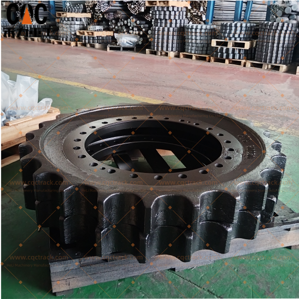
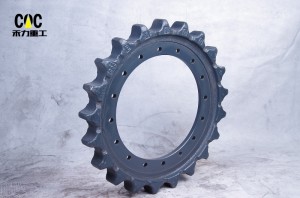
The component at the center of this technical document is the SANY SSY004621574 Track Sprocket Wheel Assembly. This OEM part number corresponds to the complete track sprocket—also referred to interchangeably in industry terminology as the drive wheel, final drive sprocket, track sprocket assy, or sprocket rim—as originally engineered for the SANY SY1250H hydraulic excavator.
The SSY004621574 part number is the official OEM designation. This number should be referenced in all procurement documentation, maintenance records, and parts catalogs to ensure accurate cross-referencing. The assembly is designed for direct 1:1 mechanical interchangeability with the original component, requiring no field modification to the final drive spline interface, mounting flange, or bolt locations.
3.2 Drive and Propulsion Compatibility
The SSY004621574 sprocket engages directly with the SANY SY1250H track chain, with tooth geometry precisely matched to the chain pitch, bushing diameter, and link spacing. Proper sprocket-to-chain compatibility is essential: the sprocket forms the mechanical linkage between the final drive and the track system. No high-quality sprocket → no stable travel performance. This is why accuracy, tooth hardness, and long-term durability are critical concerns for global buyers from rental fleets to construction contractors.
The assembly accommodates the torque output from the 2 × 18 L final drives, transmitting motive force to the track chain. The design features a robust, non-slip connection, typically pressed onto and keyed to the final drive output shaft.
3.3 Supplier Brand and Certifications
The supplier for this assembly is CQC TRACK (Heli Machinery Manufacturing Co., Ltd.) . The company was established in 2005 and is engaged in the production, manufacturing, and sales of construction machinery parts. Its main business covers excavator and bulldozer undercarriage parts, including track rollers, carrier rollers, sprockets, idlers, track chain assemblies, and track shoes. The manufacturing facility holds ISO 9001:2015 certification and operates under rigorous quality management systems.
CQC TRACK delivers durable, cost-effective solutions for excavators, bulldozers, and drilling rigs operating in the toughest environments. The supplier‘s product range includes full undercarriage components for Komatsu, Caterpillar, Hitachi, Liebherr, and more.
The supplier functions as an OEM manufacturer and source factory, providing direct access to the production source without intermediate distributors or trading companies. This direct factory supply model enables both OEM quality standards and factory-direct pricing, eliminating markups that typically arise from multi-tier distribution channels.
4. Engineering Deconstruction: Anatomy of the SSY004621574 Sprocket Assembly
The track sprocket wheel assembly is a precision-engineered power transmission component comprising multiple interacting design features. Unlike track rollers which primarily manage load bearing, the sprocket‘s sole function is efficient torque transmission from the final drive to the track chain—a function that demands exceptional tooth profile accuracy, surface hardness, and structural integrity under continuous cyclic loading.
4.1 Forged Sprocket Body
Function: The sprocket body forms the structural mass of the assembly. It transmits the full torque output from the final drive through the tooth profile to the track chain bushings. The sprocket must resist tooth breakage, plastic deformation, and fatigue cracking under the extreme cyclic loads encountered in mining applications.
Material Selection: The sprocket is fabricated from premium carbon alloy steel using a closed-die forging process that refines the metallic grain structure. Typical material grades for sprockets in the 120-ton excavator class include 42CrMo4 (EN 10083 standard) or equivalent high-strength carbon alloy steels. Forged construction, rather than casting, provides exceptional tensile strength and impact toughness, significantly reducing the risk of tooth breakage or core cracking under high-stress conditions compared to cast alternatives.
The forging process aligns the metal‘s grain flow along the component‘s principal stress axes, delivering directional strength and fatigue resistance that cast equivalents cannot achieve. For a sprocket that will endure millions of tooth–bushing engagement cycles throughout its service life, forging is the appropriate manufacturing approach.
Manufacturing Method: The sprocket blank is first rough-forged from billets of certified alloy steel, then precision-machined to final dimensions using CNC equipment. All critical interfaces—including the spline bore, mounting flange, and bolt holes—are machined on CNC equipment to exact OEM tolerances, ensuring a perfect, direct bolt-on replacement without modification and guaranteeing precise alignment with the final drive output shaft.
4.2 Tooth Profile and Engagement Geometry
Function: The sprocket teeth are the primary working surfaces, engaging with the track chain bushings to convert rotational torque into linear tracked motion. The tooth geometry defines the engagement characteristics, load distribution, and wear behavior of the entire propulsion interface.
Design Parameters: The sprocket tooth profile is engineered to achieve consistent, progressive engagement with the track chain bushings. The design incorporates:
- Tooth pitch precisely matched to the track chain link spacing to ensure uniform load distribution across all engaged teeth
- Tooth width sized to accommodate the full bushing contact area while allowing necessary clearance for dirt and debris evacuation
- Tooth root radius optimized to minimize stress concentration at the critical tooth–body junction where fatigue cracks most commonly initiate
- Tooth flank angle designed to promote smooth bushing entry and exit, reducing impact loads during each engagement cycle
For the SY1250H, with its 125-ton operating weight and 3,468 N·m maximum torque, the sprocket tooth geometry must accommodate substantial engagement forces while maintaining precise alignment with the track chain.
CNC-Machined Precision: The sprocket is precision-machined on CNC equipment to exact OEM tolerances. This precision ensures smooth power transmission, reduced vibration, and lower wear on the chain links and bushings—factors that extend the total undercarriage lifespan.
4.3 Spline Interface / Mounting Hub
Function: The spline interface (or keyed mounting hub) provides the mechanical connection between the sprocket and the final drive output shaft. This interface must transfer the full torque output without relative rotation (splines stripping or keys shearing) while allowing for field installation and removal.
Design Configuration: Depending on the specific SY1250H final drive design, the sprocket interfaces via:
- Spline drive – Internal splines machined into the sprocket hub engage with external splines on the final drive output shaft. The spline teeth are precision-formed to ensure full contact across the engaged length, distributing shear loads evenly across all spline teeth.
- Keyed shaft – A keyway machined into the sprocket bore accepts a square or rectangular key fixed to the output shaft, providing positive torque transmission in both forward and reverse directions.
Torque Capacity: The interface is designed to handle the peak torque output of 3,468 N·m without permanent deformation or wear-induced clearance accumulation. Bolts or retaining hardware secure the assembly axially on the final drive shaft, typically torqued to specifications of 450–500 N·m (dry torque), comparable to similar-size excavator class specifications.
4.4 Mounting Bolt Configuration
Function: The sprocket is secured to the final drive hub using a series of high-strength mounting bolts. These bolts must maintain clamp load under cyclic loading, vibration, and thermal expansion without loosening or fatigue failure.
Specifications: The bolt circle diameter, number of bolts, and bolt size are precisely matched to the OEM final drive configuration. Typical fastener class for sprocket mounting in this size range is Grade 12.9 high-strength alloy steel bolts, torque applied in a star pattern to ensure uniform loading of the mounting flange.
4.5 Corrosion-Resistant Coating
Function: The finished sprocket receives a protective coating to resist corrosion during storage, transport, and field operation.
Coatings Applied: CQC TRACK sprockets are finished with a manganese or zinc phosphate coating that absorbs oil and inhibits rust. This coating provides superior protection against corrosion during storage and operation, and offers an excellent base for paint adhesion if required for site specifications.
5. Material Science and Heat Treatment Protocol
Material metallurgy and heat treatment are the defining differentiators between high-grade mining sprockets and standard-duty replacements. The SSY004621574 assembly employs a graded material and thermal processing protocol specifically optimized for the 125-ton class loading conditions characteristic of the SY1250H.
5.1 Base Material Specification
The sprocket body is forged from premium carbon alloy steel, typically specified as 42CrMo4 (EN 10083) or a functionally equivalent high-strength grade. For heavy-load sprocket applications, grades such as 40Cr or 35Mn are also utilized, which provide outstanding strength and fatigue resistance ensuring the sprocket can withstand constant high-load operations.
The 42CrMo4 composition includes approximately: 0.38–0.45% carbon (for hardness capability), 0.9–1.2% chromium (for hardenability and wear resistance), 0.15–0.30% molybdenum (for strength at elevated temperatures and temper resistance), and manganese (for deoxidation and hardenability). This chemistry produces an alloy that responds well to heat treatment, achieving high strength while maintaining acceptable toughness for impact resistance.
5.2 Heat Treatment Process
High-performance sprocket assemblies incorporate a multi-stage heat treatment protocol.
Quenching and Tempering (Q&T): After forging and rough machining, the sprocket undergoes quenching and tempering. Standard processes include quenching and tempering followed by surface induction hardening. The sprocket is heated to austenitizing temperature (850–900°C), rapidly quenched in oil to transform the microstructure to martensite, then tempered at an intermediate temperature (typically 400–600°C) to reduce internal stresses while preserving high hardness. This establishes the baseline mechanical properties of the entire sprocket body prior to surface treatment.
Induction Hardening on Tooth Flanks: The sprocket teeth receive controlled induction hardening to achieve a deep, uniform surface hardness (typically 55–58 HRC). Induction hardening uses an electromagnetic coil to rapidly heat only the surface layer of the teeth, followed by immediate quenching. This process is precisely controlled to achieve a hardened case depth of 5–8 mm on the tooth flanks and contact surfaces.
The wear-resistant technology of SANY‘s own “four wheels and one belt” undercarriage components utilizes high-wear-resistant alloy steel materials, with forging or casting forming processes, and integral profiling quenching technology applied to the tooth surfaces. This provides energy efficiency, uniform surface hardened layer structure, high wear resistance, and stable quality, significantly extending product durability and service life. For sprockets in heavy-duty excavators, advanced surface treatment technologies such as QPQ (Quench-Polish-Quench) salt bath nitriding may also be employed to achieve elevated surface hardness (58–62 HRC) while maintaining core toughness (28–32 HRC).
5.3 Hardness Profile Rationale
The sprocket exhibits a graduated hardness profile that maximizes wear resistance while maintaining core toughness and impact absorption capability:
- Tooth Surface: HRC 55–58 (or 58–62 with advanced treatments). This high surface hardness provides exceptional abrasive wear resistance against the track chain bushings, dramatically increasing resistance to wear and preventing premature “hook” formation on the teeth.
- Subsurface (Case Depth 5–8 mm): Gradually decreasing hardness from the surface to the core, providing a transition zone that supports the hard surface while resisting crack propagation.
- Core: Lower hardness (approximately HRC 28–32) providing toughness and impact absorption capacity that allows the sprocket to withstand the shock loads encountered when the excavator traverses rocky terrain or impacts obstacles.
This graduated design has two critical advantages: The hard surface resists abrasive wear from track chain bushing contact, significantly extending service life. The tough core absorbs impact loads and resists crack propagation from the tooth root, preventing catastrophic tooth breakage that would take the machine out of service. The precision induction hardening provides uniform case depth across all teeth, ensuring consistent wear characteristics and predictable service life.
5.4 Hardness Validation
Component hardness is verified after heat treatment using calibrated Rockwell hardness testers. The 100% sampling ensures that every production batch meets the required surface and core hardness specifications.
6. MTG Milling Technology: The Quality Differentiator
6.1 What Is MTG Milling?
MTG milling (Multi-Tooth Generation high-precision milling) is an advanced CNC machining methodology applied to the tooth profile of the sprocket after heat treatment. Unlike conventional milling that may rely on broader tolerances or lower-precision indexing, MTG technology achieves superior dimensional accuracy and surface finish consistency across the entire tooth set.
6.2 Technical Principles
The MTG process employs precision-indexed multi-axis CNC machining with specialized tooling designed specifically for sprocket tooth generation. The process ensures that the pitch circle diameter (PCD) of the sprocket matches the track chain pitch to a tolerance level not achievable with conventional manufacturing methods. Equally important, the tooth-to-tooth spacing across the full circumference of the sprocket is maintained within a uniformly tight tolerance, ensuring that every tooth engages the track chain bushings with identical geometry.
The MTG milling method also produces a superior surface finish on the tooth working surfaces, reducing initial wear-in and promoting consistent long-term engagement with the track chain bushings.
6.3 Why MTG Matters for SY1250H Sprockets
For a 125-ton excavator operating in mining environments, the demands on sprocket precision are severe:
- Uniform load distribution reduces localized overloading of individual teeth that would accelerate wear and increase the risk of tooth breakage.
- Reduced vibration during travel extends the service life of the entire undercarriage system, including bushings, rollers, and the final drive itself.
- Predictable wear patterns allow fleet maintenance managers to plan sprocket replacements based on hour intervals rather than reacting to unexpected failures.
MTG-machined sprockets achieve a level of tooth-to-tooth consistency that standard-milled equivalents cannot match. The investment in MTG technology pays dividends in extended service life and predictable undercarriage performance.
6.4 Compatibility with OEM Specifications
CQC TRACK sprockets are engineered to original specifications, utilizing premium materials and manufacturing processes to deliver reliable performance. The MTG milling process ensures that the tooth profile matches the track chain geometry exactly, guaranteeing proper engagement and eliminating the risk of rapid wear due to profile mismatch. Sealing surfaces on CQC TRACK components are engineered to meet or exceed OEM specifications, ensuring proper interface with the machine‘s existing Duo-Cone seal system.
7. Operational Function and Mechanical Requirements
7.1 Primary Power Transmission
The sprocket is the singular component responsible for transferring immense torque from the final drive to the track chain. Every revolution of the final drive output shaft is converted into linear motion of the track chain through the sprocket‘s tooth engagement with the chain bushings.
The mechanical sequence operates as follows: The travel motor rotates the final drive planetary gear train. The final drive output shaft (with splines or key) rotates the sprocket assembly. The sprocket teeth engage the track chain bushings. The pulling force moves the track chain around the undercarriage, propelling the excavator forward or backward.
No other component can compensate for a worn or failed sprocket—the sprocket must transmit the full torque output without slipping, stripping splines, or tooth failure. This is why sprocket failure can lead to catastrophic downtime and costly damage to the entire undercarriage system.
7.2 Tooth Engagement Dynamics
During each revolution of the sprocket, each tooth engages with a track chain bushing twice (once as the tooth enters the bushing, once as it exits). Over the service life of a sprocket, each tooth may undergo millions of engagement cycles. The dynamics of this engagement are complex:
- Entry impact: As a sprocket tooth approaches a bushing, the tooth tip initially contacts the bushing surface before fully seating in the bushing gap. The hardness of the tooth surface determines how well it resists the initial contact impact and abrasive wear.
- Full engagement: During the power phase of rotation, the sprocket tooth pushes against the bushing, transferring tractive force to the track chain. The tooth flank geometry determines how evenly this force is distributed across the contact area.
- Exit relief: As the tooth exits the bushing, the engagement force decreases, and any debris trapped between tooth and bushing is expelled. The floating action of the bushing on the track chain pins allows for some misalignment accommodation during this phase.
7.3 Load Distribution Across Undercarriage
The sprocket does not bear the machine‘s weight—that function belongs to the bottom rollers. However, the sprocket is the source of all tractive force, and the forces it generates affect the entire undercarriage system. Key relationships include:
- Tractive force vs. wear: Higher tractive forces increase the contact pressure between sprocket teeth and bushings, accelerating wear on both components. The SY1250H tractive force capacity is scaled appropriately.
- Track tension influence: Proper track tension is critical for sprocket longevity. Tracks that are too tight accelerate wear on bushings, sprockets, idlers, and even the bearings in final drives, leading to premature failure of components.
- Turning forces: When the excavator turns, the outside track travels faster than the inside track, imposing side loads on the sprocket teeth and final drive bearings. The double-flange configuration of SY1250H sprockets provides lateral guidance during these maneuvers.
7.4 Wear Mechanisms and Failure Modes
Sprocket wear typically occurs gradually through cumulative abrasive contact, but improper operation can accelerate failure:
- Tooth profile wear: The tooth surface gradually wears down due to abrasive contact with track chain bushings. Tooth depth reduction exceeding 15–20% indicates the sprocket should be replaced, as worn teeth create excessive vibration and accelerate track shoe wear.
- “Shark fin” formation: When a new track chain is installed on a worn sprocket (or vice versa), the mismatch in wear patterns causes localized overloading, resulting in sharp, hook-like tooth profiles that increase wear rates dramatically.
- Spline/key wear: Repetitive torque peaks can cause spline teeth or keys to wear, creating backlash that translates into impact loads on the sprocket.
- Crack propagation: Fatigue cracks can initiate at tooth roots where stress concentration is highest, eventually propagating through the sprocket body.
The induction-hardened case depth of 5–8 mm is explicitly designed to provide a wear-resistant layer that withstands millions of engagement cycles before reaching the softer core material, at which point wear accelerates sharply. Extending the useful life of the case-hardened layer directly translates to longer sprocket service life before replacement becomes necessary.
8. Quality Assurance Framework
8.1 ISO 9001:2015 Certification
The manufacturing facility maintains ISO 9001:2015 certification across all production activities. This certification requires documented quality management systems governing:
- Raw material supplier qualification and incoming inspection
- In-process inspection protocols at each manufacturing stage
- Non-conformance handling and corrective action procedures
- Calibration and maintenance of inspection and test equipment
- Continuous improvement metrics and management review cycles
The quality management system ensures that differences in dimensional adherence between CQC TRACK components and OEM specifications are virtually eliminated, with every part verified against exact requirements before leaving the factory.
8.2 Production Quality Gates
Each production batch of the SSY004621574 assembly undergoes multiple quality control gates:
Incoming Material Verification:
- Chemical composition analysis of all forging stock prior to machining
- Mechanical properties testing (tensile strength, yield strength, elongation, hardness)
Forging and Heat Treatment Validation:
- Uniformity checks of the closed-die forging process
- Quenching and tempering cycle verification to ensure proper microstructure transformation
- Induction hardening case depth measurement on destructively tested samples
Dimensional Inspection (100%):
- Pitch circle diameter verification to ensure proper chain fit
- Tooth-to-tooth spacing confirmation using coordinate measurement
- Spline bore or keyway dimensions checked against OEM drawings
- Bolt hole positions and tolerances verified
Hardness Testing:
- Sampling verification of surface hardness on induction-hardened teeth using calibrated Rockwell hardness testers (HRC scale)
- Case depth measurement on cross-sectioned samples
Final Visual Inspection:
- All completed assemblies receive final visual inspection for surface finish, coating integrity, and labeling accuracy
- Phosphate coating uniformity verified
8.3 Non-Destructive Testing
Critical components undergo Magnetic Particle Inspection (MPI) to detect surface and near-surface cracks that could lead to in-service failure. This method is particularly effective for detecting fatigue crack initiation at tooth root radii before components are shipped to customers.
8.4 Traceability
Production lot numbers are stamped or etched onto each sprocket assembly. These traceability codes link the finished component back through all manufacturing documentation, including material certificates, heat treatment records, hardness test results, dimensional inspection logs, and final approval records. For international customers navigating warranty claims, failure analysis investigations, or compliance audits, this traceability provides auditable documentation.
8.5 Performance Lifetime
CQC TRACK heavy-duty undercarriage components are engineered to achieve extended service life in demanding mining applications. The combination of forged alloy steel construction, deep-case induction hardening (5–8 mm), precision MTG milling, and rigorous quality controls—all backed by ISO 9001:2015 certification—directly translates to longer operational service life before sprocket replacement becomes necessary. Given the synergized relationship between sprockets and other undercarriage wear parts, many aftermarket professionals recommend replacing sprockets and drive components as matched sets with corresponding hardware to ensure that matching wear cycles deliver the best value for money. Industry experts further advise that replacing individual components is generally pointless, because the new part cannot compensate for the wear of the old parts.
9. Supply Chain Advantages: OEM Manufacturer, Source Factory
9.1 Manufacturer Direct Model – OEM Manufacturer and Source Factory
The buyer works directly with CQC TRACK (Heli Machinery Manufacturing Co., Ltd.) —a primary manufacturer of undercarriage components, not a distributor or trading company. The company was established in 2005 and is engaged in the production, manufacturing, and sales of construction machinery parts. Its main business covers excavator and bulldozer undercarriage parts, including track rollers, carrier rollers, sprockets, idlers, track chain assemblies, and track shoes.
This direct supply model eliminates multiple tiers of intermediaries:
- No distributor markups
- No trading company commissions
- No regional importer fees applied
- Direct communication between the end user and the manufacturing engineering team
The result is OEM quality at factory-direct pricing—a combination rarely available through traditional distribution channels where markups for construction equipment parts tend to be substantial.
9.2 OEM and ODM Manufacturing Capability
For customers with specific requirements beyond the standard SSY004621574 specification, CQC TRACK offers OEM and custom manufacturing services. Buyers may provide drawings, technical specifications, or physical samples, and the engineering team will produce components to those requirements. This capability is particularly relevant for customers operating:
- Machines with non-standard undercarriage configurations
- Modified track chain geometries requiring custom sprocket profiles
- Special material requirements for extreme operating conditions (e.g., high abrasion, saltwater exposure)
- Private-label branding on undercarriage components for volume distributors
The company maintains engineering and tooling resources spanning multiple major brands including Komatsu, Caterpillar, Hitachi, and Liebherr alongside their work with SANY machinery, enabling cross-application engineering expertise.
9.3 Production Capacity and Lead Times
CQC TRACK operates with a 20-acre industrial park, a factory area exceeding 10,000 square meters, over 50 skilled employees, and a cumulative investment exceeding RMB 10 million. This production capacity supports both routine sprocket replacement orders and volume procurement for distributors.
Order lead times typically range from 15 to 30 days for standard production quantities, depending on current production scheduling and the specific configuration ordered. Rush orders based on current capacity availability may be accommodated with advance coordination.
9.4 Logistics and Global Export Capacity
CQC TRACK has established logistics partnerships supporting shipments to major global markets including North America, Europe, Africa, Southeast Asia, and the Middle East. The company possesses extensive experience in packaging undercarriage components for international sea freight, with appropriate corrosion protection for marine transit.
9.5 Volume Pricing and OEM Supply Agreements
For volume buyers—including equipment dealers, fleet operators, and parts distributors—the manufacturer offers tiered pricing based on annual purchase volumes and ongoing supply agreements with guaranteed pricing and delivery windows. OEM contract manufacturing agreements can be structured to accommodate private labeling, specification modifications, and exclusive distribution arrangements for qualified partners.
CQC TRACK‘s OEM manufacturer and source factory operating model provides a distinct supply chain advantage for global buyers who need to maintain parts availability for SY1250H excavators deployed in remote mining and construction sites worldwide. The combination of direct factory pricing, engineering capability, and logistics infrastructure makes this supplier a suitable partner for both single-unit replacement orders for individual machines and volume stocking arrangements for distributors.
10. Installation and Maintenance Considerations
10.1 Installation Parameters
The SSY004621574 sprocket assembly is designed for direct mechanical interchangeability with the original component. Installation on the SY1250H requires:
- Cleaning the final drive mounting surfaces to remove debris, old seal material, and corrosion
- Verifying that the spline or keyway is free of damage or excessive wear that would prevent proper torque transmission
- Installing the sprocket on the final drive output shaft with appropriate seating force
- Torquing the retaining bolts to the manufacturer’s specification (typically in the range of 450–500 N·m, dry torque, comparable to similar heavy excavator bolt torque requirements)
- Applying the torque in a star pattern across multiple passes to ensure uniform load distribution
Proper installation torque is critical; under-torquing can allow axial movement that damages the spline interface, while over-torquing can distort the mounting flange or stretch bolts into the plastic deformation range where they lose clamp load capacity.
10.2 Condition Monitoring and Replacement Indicators
Fleet maintenance personnel should inspect sprockets at regular intervals (typically every 500–1,000 operating hours for mining applications). Key indicators that require sprocket replacement include:
- Tooth depth reduced by more than 15–20% from original specification. Worn teeth create excessive vibration and accelerate track shoe wear.
- “Shark fin” or hooked tooth profiles—sharp, asymmetrical wear patterns that indicate mismatched chain–sprocket wear.
- Visible cracking at the tooth root fillets, particularly under magnetic particle inspection or close visual examination.
- Spline or keyway wear evidenced by rotational play between sprocket and final drive shaft.
- Corrosion or impact damage that compromises tooth integrity.
According to industry failure analysis, chassis system failures account for more than 35% of total excavator failures, and 80% of these failures are caused by failure to detect component wear in time. Regular sprocket inspections are therefore not optional—they are a cost-effective strategy to prevent downstream damage.
10.3 Pre-Installation Checks
When installing a new sprocket, the track chain should also be evaluated for wear. The use of a new sprocket with a worn track chain—or vice versa—accelerates wear on both components due to mismatch in engagement geometry. The single most important factor is replacing all components at one time that have been operating together on a specific piece of heavy machinery. Using a new chain with worn sprockets—or vice versa—is a shortcut to rapid failure.
10.4 Storage and Handling Guidelines
When stored before installation, sprockets should be kept in dry conditions, preferably wrapped in vapor-proof packaging to prevent corrosion on machined surfaces. Sprockets should be stored flat on a pallet or shelf; stacking sprockets directly on top of each other can damage tooth profiles.
Dropping or impacting sprockets can cause hidden cracking that may not be visible to the naked eye but will propagate under load. Handling should be by lifting the assembly using appropriate lifting equipment, not by rolling or dropping. The phosphate coating applied to CQC TRACK sprockets provides good corrosion resistance during storage, but extended storage in high-humidity environments should be avoided or supplemented with additional vapor corrosion inhibitor (VCI) packaging for long-term warehouse storage.
11. Technical Specifications Summary
| Parameter | Specification |
|---|---|
| OEM Part Number | SSY004621574 |
| Component Name | Track Sprocket Wheel Assembly / Final Drive Sprocket / Drive Wheel |
| Host Machine Model | SANY SY1250H Hydraulic Excavator |
| Machine Operating Weight | 125,000 kg |
| Engine | Cummins QSK23, 567 kW @ 1,800 rpm |
| Max Torque | 3,468 N·m @ 1,350 rpm |
| Material | Forged carbon alloy steel (42CrMo4 grade or equivalent) |
| Manufacturing Method | Closed-die forging + CNC precision machining |
| Tooth Profile Generation | MTG multi-axis CNC milling |
| Surface Treatment | Induction hardening on tooth flanks |
| Surface Hardness (Teeth) | HRC 55–58 (with optional advanced treatments achieving HRC 58–62) |
| Core Hardness | HRC 28–32 |
| Hardened Case Depth | 5–8 mm |
| Phosphate Coating | Manganese or zinc phosphate (corrosion-resistant) |
| Mounting Torque | 450–500 N·m (dry torque, per comparable class specifications) |
| Quality Certifications | ISO 9001:2015 Certified Manufacturing |
| Non-Destructive Testing | Magnetic Particle Inspection (MPI) |
| Manufacturer | Heli Machinery Manufacturing Co., Ltd. (CQC TRACK) |
| Factory Established | 2005 |
| Supply Model | OEM Manufacturer / Source Factory (Direct factory supply) |
| Production Lead Time (Std Qty) | 15–30 days |
| Global Logistics | North America, Europe, Africa, Southeast Asia, Middle East |
12. Conclusion
The SANY SY1250H SSY004621574 Track Sprocket Wheel Assembly from CQC TRACK represents a fully engineered power transmission component manufactured with forging, controlled induction hardening (5–8 mm case depth, HRC 55–58 surface hardness), MTG precision tooth milling, and direct factory supply economics. For fleet managers, procurement specialists, and distributors optimizing their SANY excavator parts strategy, this assembly delivers documented performance characteristics matched to the 125-ton mining excavator platform.
The closed-die forging process—rather than casting—ensures the directional strength required to resist tooth breakage and fatigue cracking under high-stress conditions. The graduated hardness profile maximizes wear resistance while maintaining core toughness and impact absorption capability. The MTG milling technology ensures consistent tooth geometry across the full circumference, promoting smooth engagement and extended service life.
The manufacturer‘s direct sourcing model as an OEM manufacturer and source factory provides a supply chain advantage over multi-tiered distribution channels, supporting both single-unit replacement orders for individual machines and volume procurement for distributors. With ISO 9001:2015 certified manufacturing, established logistics to major global markets, OEM and custom manufacturing capability, and documented extended service life, CQC TRACK positions the SSY004621574 assembly as a technically robust and economically efficient solution within the large excavator undercarriage aftermarket.
The SY1250H is built to operate for 25,000 hours in mining conditions. Every component in its undercarriage must be up to the task. The choice of sprocket directly affects track tension management, final drive longevity, and overall machine availability. The SSY004621574 assembly from CQC TRACK is engineered to meet that standard—and to help global mining and construction operations keep their heavy equipment productive and profitable across the full service life of the machine.
For procurement inquiries, technical specifications, custom manufacturing requirements, or to discuss OEM supply agreements and private-label branding, direct contact with the manufacturer is available through official CQC TRACK channels.
Products categories
-
Excavator Undercarriage parts sprocket EX100 EX...
-

Komatsu 2092751172 2092751173 2092751170 PC800 ...
-

SANY SSY005661438 SY650 Final Drive Wheel Assem...
-

Sell SY55/65 Excavator sprocket with OEM qualit...
-

XCMG XR400 Drive Sprocket Wheel For Drilling Ri...
-

Caterpillar 1243296 1792929 E345 E349 Track Spr...


