
XCMG 800348149 XE900/XE950 Track Idler Assy/Guide Wheel Group/OEM quality undercarriage source manufacturer&factory-CQCTRACK


Technical Specification: Track Idler / Guide Wheel Assembly (Front Idler)
Part Identification:
- Compatible Machine Models: XCMG XE900, XE950 Crawler Excavators.
- Application: Undercarriage System, Front Guidance and Tensioning.
- Component Aliases: Front Idler, Guide Idler, Track Guide Wheel.
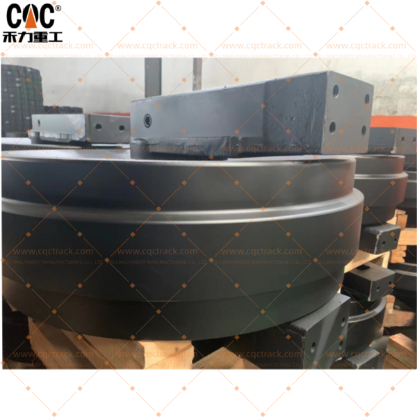
1.0 Component Overview
The Track Idler / Guide Wheel Assembly is a fundamental and heavy-duty component positioned at the front of the excavator’s undercarriage frame. Serving as the passive counterpart to the drive sprocket, its primary functions are to guide the track chain into a continuous loop and to provide the mechanical interface for adjusting track tension. This assembly is specifically engineered to endure significant impact loads, constant abrasive wear from the track chain, and the harsh environmental conditions typical of large-scale mining and earthmoving operations.
2.0 Primary Function & Operational Context
The core engineering functions of this assembly are:
- Track Guidance and Path Definition: It acts as the forward directional pivot for the track chain, reversing its path after ground contact and guiding it smoothly back towards the drive sprocket, thereby defining the track’s complete loop.
- Track Tension Adjustment Mechanism: The idler is mounted on a robust sliding mechanism connected to a hydraulic or grease-operated tensioning cylinder. This allows for precise forward and backward adjustment of the idler, which directly controls the track sag. Correct tension is paramount for optimal power transfer, reduced rolling resistance, and maximizing the service life of the entire undercarriage system.
- Primary Impact and Shock Absorption: Due to its forward-facing location, the idler is the first point of contact with obstacles such as rocks and debris. Its design prioritizes the absorption and dissipation of substantial shock loads to protect the undercarriage frame and final drives from damage.
- Track Stabilization and Containment: The integrated flanges on the idler wheel work to maintain the lateral alignment of the track chain, preventing derailment during turning maneuvers and operation on uneven or sloped terrain.
3.0 Detailed Construction & Key Sub-Components
This assembly is a precision-engineered, sealed system comprising:
- 3.1 Idler Wheel (Rim): A large-diameter, robust wheel with a precisely machined and hardened running surface. Its wide profile ensures stable contact with the track chain links, distributing load effectively.
- 3.2 Flanges: Integral lateral guides on both sides of the rim. These are critical for containing the track chain, preventing lateral slippage and derailment under side loads. They are built to resist impact deformation and abrasive wear.
- 3.3 Internal Bearing and Bushing System:
- Shaft: A high-strength, hardened and ground steel stationary shaft that provides the fixed axis of rotation.
- Bearings/Bushings: The idler housing rotates on the shaft via a set of large, heavy-duty tapered roller bearings or bronze bushings, selected for their exceptional capacity to handle extreme radial loads and occasional axial (thrust) forces.
- 3.4 Multi-Stage Sealing System: This is the most critical subsystem for determining service life. It typically employs a labyrinth-style design, incorporating a primary radial face seal, secondary dust lips, and often a grease-filled chamber. This multi-barrier defense is essential for effectively excluding highly abrasive contaminants (e.g., silica dust, slurry) and retaining the high-performance grease within the bearing cavity.
- 3.5 Mounting Bracket and Sliding Mechanism: The assembly includes a forged or cast bracket with precisely machined sliding surfaces. These interfaces connect to the guides on the undercarriage frame and the push-rod of the track tensioning cylinder, enabling precise and reliable track tension adjustment.
4.0 Material & Performance Specifications
- Material: High-Carbon Alloy Steel Casting or Forging.
- Hardness: The rim running surface and flanges are through-hardened or induction-hardened to a typical range of 55-62 HRC. This provides an optimal balance of high impact resistance and superior resistance to abrasive wear.
- Lubrication: Pre-filled with a high-temperature, extreme-pressure (EP) lithium-complex grease. A standard grease fitting is typically provided for periodic re-lubrication during service intervals to help purge the seal chamber of minor contaminants and extend operational life.
5.0 Failure Modes & Maintenance Considerations
- Wear Limits: Serviceability is determined by measuring the reduction in flange height and rim diameter against XCMG’s specified maximum wear limits. Severely worn flanges significantly increase the risk of track derailment.
- Common Failure Modes:
- Flange Spalling and Fracture: Cracking, chipping, or breakage of flanges due to high-impact loads from obstacles.
- Rim Grooving and Concave Wear: Abrasive wear from the track chain links forming grooves or a concave profile on the rim, leading to improper track contact and accelerated chain wear.
- Bearing Seizure: A catastrophic failure often caused by seal failure, which allows abrasive particles to contaminate the lubricant. A seized idler will not rotate, causing rapid, severe wear to the track chain bushings and the idler itself.
- Sliding Mechanism Seizure: Corrosion, damage, or contamination of the sliding brackets can prevent tension adjustment, locking the idler in place.
- Maintenance Practice: Regular inspection for free rotation, structural integrity, and any signs of bearing failure (noise, play) is essential. Track tension must be checked and adjusted strictly according to the manufacturer’s operational manual. It is a critical best practice to replace the idler in conjunction with the track chain and other undercarriage components to prevent accelerated, mismatched wear.
6.0 Conclusion
The XCMG XE900/XE950 Track Idler / Guide Wheel Assembly is a vital component for ensuring the mobility, stability, and longevity of the excavator’s undercarriage. Its roles in guidance, tensioning, and impact absorption are indispensable for reliable operation in demanding environments. Proactive monitoring, correct maintenance procedures, and system-synchronized replacement are essential disciplines for minimizing downtime and controlling operating costs. The use of genuine or certified OEM-equivalent parts is paramount to guarantee the required dimensional accuracy, material properties, and sealing performance, thereby safeguarding the significant investment in this heavy equipment.
Products categories
-

High Quality Roller Ex70 Front Idler Guide Whee...
-

Caterpillar 990161 4I7337 E312 / E120B Track Id...
-

HITACHI zax200-5A/ZX200-5G(P/N:9303011) front i...
-

Komatsu PC1000 front Idler /21n-30-13111 from C...
-

Sell DX300 Bulldozer Excavator undercarriage sp...
-

VOLVO excavator undercarriage components manufa...


