
HYUNDAI 81E700662 81E700633GG 81E700664 81QB10011 81QB10050 R500 R520 HX520 Track Final Drive Sprocket Wheel Assy / Heavy duty Crawler EXC undercarriage part Source Mnuafacturer and Factory / CQC TRACK


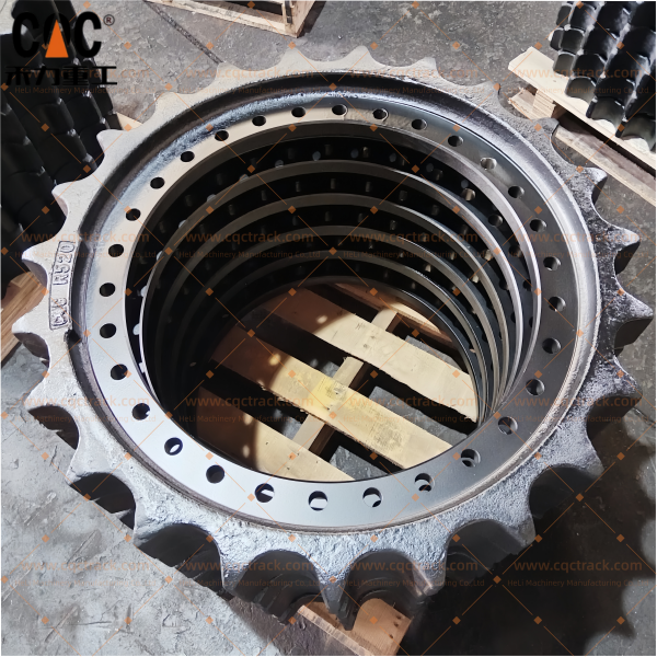
HYUNDAI Final Drive Sprocket Wheel Assembly: Heavy-Duty Undercarriage Solutions for R500, R520 & HX520 Excavators
In the realm of large hydraulic excavators, the 50-ton class represents a critical segment where power, durability, and operational efficiency converge. HYUNDAI’s R500, R520, and HX520 models are widely deployed in heavy mining support, large-scale quarry operations, mass earthmoving, and infrastructure megaprojects. At the heart of these machines’ mobility lies the Final Drive Sprocket Wheel Assembly—the critical interface where hydraulic power transforms into tractive force, enduring the highest torque loads of any undercarriage component.
This article delivers a comprehensive technical analysis of HYUNDAI final drive sprocket assemblies, focusing on OEM cross-reference numbers 81E700662, 81E700633GG, 81E700664, 81QB10011, and 81QB10050. It explores the engineering specifications, material requirements, application compatibility, manufacturing processes, and the strategic advantages of sourcing from a source manufacturer and factory such as CQC TRACK.
1. The Final Drive Sprocket: Power Transmission at Its Most Critical
The final drive sprocket wheel assembly represents the terminal element of the excavator’s power train. Unlike smaller undercarriage components that manage load and guidance, the sprocket is the driving force—its teeth engage the track chain bushings to propel the machine forward or backward.
For large excavators in the 50-ton class (R500, R520, HX520), the final drive sprocket must withstand:
- Peak Torque Output: Final drive reduction ratios typically range from 60:1 to 100:1, multiplying engine torque to levels exceeding 200,000 Nm at the sprocket.
- Cyclic Impact Loading: Each tooth engages and disengages with track bushings thousands of times per operating hour, subjecting the component to continuous fatigue cycles.
- Abrasive Wear: Contact with track bushings in abrasive environments (rock dust, sand, slurry) accelerates material loss on tooth surfaces.
- Lateral Stress: Turning operations and slope work impose side loads that stress the sprocket mounting interface and final drive bearings.
Given these demands, the final drive sprocket assembly is engineered to the highest standards of material science, heat treatment, and dimensional precision.
2. OEM Part Number Cross-Reference and Application Mapping
The five part numbers covered in this article represent different final drive sprocket configurations used across HYUNDAI’s large excavator platforms:
| Part Number | Compatible Models | Component Type | Application Notes |
|---|---|---|---|
| 81E700662 | R500-7, R500-9, R500LC | Bolt-on sprocket rim | Standard configuration for R500 series; field-replaceable rim design |
| 81E700633GG | R500-7, R500-9, R500LC | Complete final drive assembly | Includes planetary gear set, hub, and sprocket rim |
| 81E700664 | R520-7, R520-9, R520LC | Bolt-on sprocket rim | Heavy-duty variant; reinforced tooth profile for higher impact applications |
| 81QB10011 | HX520, HX520L, HX520NL | Bolt-on sprocket rim | Next-generation HX series; optimized tooth geometry |
| 81QB10050 | HX520, HX520L, HX520NL | Complete final drive assembly | Integrated design with advanced sealing and bearing systems |
2.1 Model Series Overview
| Model | Operating Weight | Platform Generation | Typical Applications |
|---|---|---|---|
| R500 | ~48–52 t | R-series (Dash 7, 9) | Large-scale earthmoving, quarry operations, mining support |
| R520 | ~50–54 t | R-series (Dash 7, 9) | Heavy excavation, rock handling, mass grading |
| HX520 | ~50–55 t | HX-series (Next generation) | Heavy mining, large infrastructure, demolition |
2.2 Compatibility Notes
- The 81E700662 and 81E700664 sprocket rims are interchangeable on the same final drive hub, allowing operators to select tooth profiles optimized for specific applications.
- The 81E700633GG and 81QB10050 complete final drive assemblies include the planetary gear reduction unit, requiring verification of gear ratios and mounting interfaces before replacement.
- HX520 models utilize updated sealing technology; the 81QB10050 assembly incorporates floating seals with enhanced contamination resistance.
3. Technical Specifications and Engineering Features
3.1 Dimensional Parameters
Precision dimensions are essential for proper fitment and track chain engagement:
| Parameter | Specification |
|---|---|
| Pitch Diameter | Matches track chain pitch (typically 216–228 mm for 50-ton class) |
| Number of Teeth | 21–25 teeth depending on configuration |
| Bolt Circle Diameter | Precision-machined to match final drive hub |
| Mounting Bolt Pattern | 12–16 high-strength bolts (grade 12.9) |
| Pilot Diameter | Ensures concentric mounting to prevent radial runout |
3.2 Material Selection
High-quality final drive sprockets for large excavators utilize forged alloy steel to achieve the required combination of strength, toughness, and wear resistance:
| Component | Material | Properties |
|---|---|---|
| Sprocket Rim | Forged 35CrMo or 40CrMnMo | High strength, impact toughness, fatigue resistance |
| Final Drive Housing | Ductile cast iron or forged steel | Structural integrity, vibration damping |
| Planetary Gears | Case-hardened 20CrMnTi or equivalent | Surface hardness with ductile core |
3.3 Heat Treatment Profile
The sprocket rim undergoes specialized heat treatment to optimize wear resistance while maintaining structural integrity:
| Parameter | Specification |
|---|---|
| Surface Hardness (Tooth Flanks & Tips) | 52–58 HRC |
| Case Depth | 8–12 mm (heavy-duty specification) |
| Core Hardness | 28–35 HRC |
| Hardness Gradient | Gradual transition prevents spalling and delamination |
For the 81E700633GG and 81QB10050 complete final drive assemblies, planetary gears are carburized and case-hardened to achieve surface hardness of 58–62 HRC with case depth of 1.5–2.5 mm, ensuring gear tooth durability under high torque.
3.4 Sealing Technology
Large excavator final drives operate in environments where contamination ingress can cause catastrophic failure. Advanced sealing systems include:
- Duo-Cone Floating Seals: Metal-faced seals with mirror-finished wear rings provide exceptional resistance to abrasive particles.
- Seal Material Options: High-temperature FKM (fluoroelastomer) for extreme environments; NBR (nitrile) for standard applications.
- Labyrinth Seals: Additional contamination barriers on the sprocket-to-hub interface.
4. Heavy-Duty Design Considerations for 50-Ton Class Excavators
4.1 Torque Capacity
The R500, R520, and HX520 excavators deliver engine power in the 300–400 HP range, with final drive reduction ratios typically between 70:1 and 90:1. The sprocket must withstand peak torque outputs exceeding:
| Parameter | Value |
|---|---|
| Maximum Drive Torque | 180,000–220,000 Nm |
| Tooth Load per Engagement | 25,000–35,000 N |
| Fatigue Cycles (Service Life) | 5–8 million engagement cycles |
4.2 Tooth Profile Optimization
Modern sprocket designs for HX520 models (81QB10011) incorporate involute tooth geometry that:
- Distributes engagement forces evenly across the tooth flank
- Reduces impact stress during initial bushing contact
- Minimizes noise and vibration during operation
- Extends bushing life by up to 15% compared to conventional profiles
4.3 Field Serviceability
The bolt-on rim design of 81E700662, 81E700664, and 81QB10011 allows for field replacement of the sprocket rim without disturbing the final drive housing. This feature:
- Reduces downtime from 2–3 days to 4–6 hours
- Eliminates the need for specialized final drive service tools
- Extends final drive component life by preserving housing and bearing integrity
5. Manufacturing Process: Source Manufacturer and Factory Capabilities
As a source manufacturer and factory, CQC TRACK employs vertically integrated manufacturing processes that ensure complete control over quality, consistency, and traceability.
5.1 Forging and Forming
Sprocket rims begin as cut billets of 35CrMo or 40CrMnMo steel, heated to precise temperatures and formed using high-tonnage forging presses (5,000–10,000 tons). The forging process:
- Aligns the grain structure along the tooth profile
- Eliminates internal voids and porosity
- Provides consistent material density and mechanical properties
- Achieves near-net shape, reducing material waste
5.2 Heat Treatment
Heat treatment is the most critical step in sprocket manufacturing:
| Process Step | Parameters | Purpose |
|---|---|---|
| Quenching and Tempering | 850–880°C austenitizing; oil quench; 550–650°C temper | Achieves core hardness (28–35 HRC) with optimized toughness |
| Induction Hardening | High-frequency heating; 52–58 HRC surface; 8–12 mm case depth | Hardens tooth flanks and tips to resist wear |
5.3 Precision Machining
CNC machining centers perform critical operations with tolerances maintained within ±0.05 mm:
- Tooth profile machining using dedicated hobbing or milling equipment
- Bolt hole drilling with precise position and counterbore depth
- Pilot diameter finishing for concentric mounting
- Mounting surface preparation for seal interface
5.4 Final Drive Assembly (81E700633GG / 81QB10050)
Complete final drive assemblies undergo additional manufacturing steps:
- Planetary gear manufacturing (hobbing, shaving, carburizing, grinding)
- Bearing press-fitting with controlled interference
- Floating seal installation in clean-room conditions
- Gear train assembly with shim-adjusted preload
- Final testing under simulated load conditions
6. Quality Assurance Protocols
CQC TRACK implements rigorous quality control measures to ensure every final drive sprocket assembly meets or exceeds OEM specifications.
6.1 Material Traceability
Each heat of steel is accompanied by mill test certificates (MTC) documenting chemical composition, mechanical properties, and heat treatment parameters. Traceability is maintained throughout manufacturing using batch coding systems.
6.2 Dimensional Inspection
CMM (Coordinate Measuring Machine) inspection verifies critical dimensions:
- Pitch diameter and tooth spacing within ±0.1 mm
- Bolt circle diameter and hole positioning
- Pilot diameter and concentricity
- Mounting surface flatness
6.3 Hardness Verification
Hardness traverse testing from the tooth tip to the core confirms:
- Case depth within specified range (8–12 mm)
- Gradual hardness gradient preventing delamination
- Core hardness meeting 28–35 HRC specification
6.4 Non-Destructive Testing (NDT)
Critical components undergo:
- Magnetic Particle Inspection (MPI): Detects surface and subsurface cracks in sprocket rims
- Ultrasonic Testing (UT): Verifies internal integrity of forged components
- Dye Penetrant Inspection: Confirms seal surface integrity
6.5 Final Drive Testing (Complete Assemblies)
Complete final drive assemblies (81E700633GG / 81QB10050) undergo:
- No-Load Run-In: Verifies smooth operation and gear mesh
- Pressure Testing: Confirms floating seal integrity
- Torque Verification: Ensures proper gear train assembly
- Vibration Analysis: Detects imbalance or misalignment
7. Installation and Maintenance Best Practices
7.1 Installation Guidelines
| Step | Recommendation |
|---|---|
| Bolt Torque | Use new grade 12.9 bolts; torque to manufacturer specification (typically 800–1,200 Nm depending on bolt size); follow cross-pattern sequence |
| Seal Inspection | Verify floating seal surfaces are clean and undamaged before installation |
| Concentricity Check | Confirm sprocket rim runs true after installation; maximum runout ≤0.5 mm |
| Lubrication | Fill final drive with specified oil (typically SAE 90 or 140 gear oil) to correct level |
7.2 Maintenance Practices
| Activity | Frequency | Purpose |
|---|---|---|
| Visual Inspection | Daily | Check for oil leakage, unusual noise, or loose bolts |
| Tooth Wear Inspection | 250 hours | Measure tooth thickness; compare to wear limits |
| Bolt Torque Check | 500 hours | Verify mounting bolt torque retention |
| Final Drive Oil Analysis | 1,000 hours | Detect contamination or wear particles |
| Component Replacement | At wear limit | Replace sprocket rim when tooth wear reaches 15–20% of original profile |
7.3 Wear Life Optimization
To maximize final drive sprocket service life:
- Replace sprocket rims in conjunction with track chains and bushings to maintain pitch compatibility
- Maintain proper track tension to prevent sprocket tooth overload
- Avoid operating with worn track chains, as elongated pitch accelerates sprocket wear
- For complete final drive assemblies, maintain proper oil levels and change oil at recommended intervals
8. Why Source from CQC TRACK?
As a source manufacturer and factory, CQC TRACK offers distinct advantages for international buyers seeking HYUNDAI final drive sprocket assemblies:
| Advantage | Description |
|---|---|
| Material Authenticity | Genuine forged alloy steel with full material traceability and mill test certificates |
| Vertically Integrated Manufacturing | Complete in-house control: forging, heat treatment, machining, and assembly |
| OEM Interchangeability | Precision manufacturing ensures drop-in fitment for all listed part numbers and models |
| Heavy-Duty Specifications | Enhanced case depth (8–12 mm) for 50-ton class applications |
| Quality Assurance | Comprehensive testing including CMM inspection, hardness verification, and NDT |
| Supply Chain Reliability | Finished goods inventory with lead times of 15–25 days for sprocket rims; 25–35 days for complete final drive assemblies |
| Customization Capabilities | Private labeling, custom packaging, and engineering support for ODM/OEM requirements |
9. Conclusion
The HYUNDAI final drive sprocket wheel assemblies represented by part numbers 81E700662, 81E700633GG, 81E700664, 81QB10011, and 81QB10050 are critical components for maintaining the mobility and productivity of R500, R520, and HX520 series excavators. These 50-ton class machines operate in the most demanding environments—heavy mining support, large-scale quarry operations, and mass earthmoving—where component failure translates directly into costly downtime.
For aftermarket distributors, fleet operators, and equipment rebuilders, sourcing these components from a source manufacturer and factory like CQC TRACK ensures heavy-duty durability combined with engineering precision. By leveraging advanced forging capabilities, precise heat treatment, and rigorous quality assurance, CQC TRACK delivers final drive sprocket assemblies that perform with the reliability and longevity required for the world’s most demanding excavator applications.
In the competitive global aftermarket, selecting the right undercarriage partner is not merely a procurement decision—it is a strategic investment in operational continuity, customer satisfaction, and long-term business success.
Disclaimer: Part numbers and model references are provided for cross-reference purposes only. They are intended to indicate compatibility with original equipment manufacturer (OEM) specifications. CQC TRACK is an independent source manufacturer and factory of aftermarket
Products categories
-

XCMG-XE265GK/XE270 Final Drive Sprocket Assembl...
-

SANY SSY004997367 SY850 Final Drive Sprocket Gr...
-

14532544/VOE14532544-EC700 SPROCKET DRIVE WHEEL...
-

Hitachi excavator undercarriage part Final Driv...
-

Excavator Sprocket,Professional factory OEM exc...
-

HITACHI 1020265 4388621 ZAX650 ZX650 Track Spro...


