
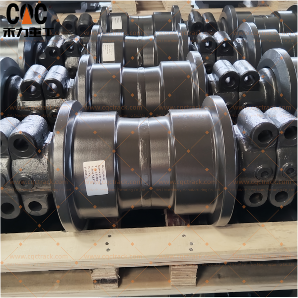
XCMG XE335C 414102203 Track Bottom Roller Assembly / CQC TRACK ‘s Heavy duty Crawler Excavator Spare parts / OEM Quality Source Manufacturer Supplies Directly


Technical White Paper
XCMG XE335C 414102203 Track Bottom Roller Assembly / CQC TRACK: Heavy-Duty Crawler Excavator Spare Parts — OEM Quality Source Manufacturer Supplies Directly
1. Executive Summary: Component Overview
XCMG stands as a globally recognized force in heavy machinery, with XE335C crawler excavator operating weight at 33.8 metric tons and standard bucket capacity ranging between 1.4 and 1.6 cubic meters, purpose-built for demanding earthmoving and construction applications. This machine relies on a highly engineered undercarriage system, wherein the bottom roller assembly plays an indispensable role.
This document provides a complete technical breakdown of the XCMG XE335C 414102203 Track Bottom Roller Assembly (CQC TRACK). Defined as a sealed and lubricated heavy-duty bottom roller, this unit directly supports the machine‘s substantial mass, transfers dynamic loads through the track chain onto the ground, and maintains proper track alignment during both straight-line travel and high-stress turning maneuvers. Engineered for high-wear environments, this assembly represents an OEM-quality replacement solution manufactured under rigorous quality protocols and supplied factory-direct.
What distinguishes this product is not merely its dimensional conformity, but the methodological rigor embedded into its production. Manufactured under China Quality Certification (CQC) framework and ISO 9001:2015 protocols, each unit emerges from a controlled system that governs metallurgical integrity, machining precision, and assembly reliability from raw material sourcing to final validation. The supplier, CQC TRACK (Heli Machinery Manufacturing Co., Ltd.) , functions as a direct-source manufacturer, eliminating the typical brokerage chain and ensuring that every component reaches the end user with certified traceability.
This white paper is structured for procurement professionals and fleet maintenance engineers. It progresses from machine model context and core operational functions, then moves into exhaustive engineering deconstruction and material specifications. Finally, it addresses quality assurance frameworks and logistics support to facilitate informed purchasing decisions.
2. XCMG XE335C Host Machine Platform and Undercarriage Context
The XCMG XE335C is a 33.8-ton hydraulic crawler excavator powered by the ISUZU AA-6HK1XQP diesel engine, delivering 190.5 kW of rated power at 2,000 rpm. This engine employs direct-injection, four-stroke, water-cooled, turbocharged configuration coupled with an air-to-air intercooler, producing a maximum torque of 872.8 N·m at 1,700 rpm. The hydraulic system features dual piston-type main pumps with a combined flow rate of 2 × 280 L/min and main safety valve pressure settings at 34.3 MPa and 37 MPa respectively.
Key undercarriage dimensions for this machine classification are as follows: overall track length on ground at approximately 3,183 mm, crawler width at 600 mm, and track gauge at roughly 2,590 mm. These parameters define the spacing and load distribution criteria that the bottom roller assembly must accommodate. The XE335C achieves a ground pressure of 66 kPa and offers gradeability of ≥35 degrees——specifications that translate directly into the vertical load and lateral thrust forces that each bottom roller assembly must be engineered to withstand.
The bottom roller positions itself between the track frame and the track chain, carrying multiple sets of rollers per undercarriage side. Understanding this relationship is critical: when the excavator operates on uneven terrain, enters trenching configurations, or performs counter-rotation turns, certain rollers bear disproportionate static and impact loads while others experience tension-related stress. A bottom roller is therefore not a simple idler——it is a high-precision load-bearing tribological system that must manage abrasion, impact fatigue, and cyclic loading simultaneously.
Beyond vertical load bearing, bottom rollers perform track alignment functions. The dual-flanged design captures the inner link groups of the track chain, preventing lateral drift that could otherwise lead to track derailment during side-slope operations or aggressive turning. Additionally, properly functioning bottom rollers ensure consistent track sag——too loose and vibration increases, too tight and power loss escalates. Maintaining the correct roller specifications is thus essential for optimizing the host machine’s travel efficiency and component lifespan across the entire undercarriage system.
3. Product Identification and Cross-Reference Matrix
Accurate procurement begins with precise part number identification. The product in discussion carries OEM Part Number 414102203, which corresponds to the complete track bottom roller assembly as engineered specifically for the XCMG XE335C and compatible with same-class XCMG crawler excavator models sharing this undercarriage configuration.
The supplier identification follows the CQC TRACK branding under Heli Machinery Manufacturing Co., Ltd. This manufacturer holds ISO 9001:2015 certification and operates under CQC product certification protocols, ensuring that engineering intent and material selection directly replicate——and in specific metrics exceed——the original equipment manufacturer‘s baseline requirements. The assembly is designed for 1:1 mechanical interchangeability without any field modification required. Installation does not necessitate rework of the track frame mounting bosses, shaft alignment bores, or fastener locations.
It is noted that certain manufacturers with dual production lines——OEM supply and aftermarket——operate China Quality Certification (CQC) frameworks through voluntary product certification conducted by the China Quality Certification Center. The CQC mark demonstrates conformance to relevant quality, safety, and performance standards, an added layer of quality verification for internationally traded construction equipment components.
4. Engineering Deconstruction: Anatomy and Core Components
The track bottom roller assembly is a composite unit comprising multiple precision-manufactured subsystems. The following sections detail each component’s function, material selection, and manufacturing methodology.
4.1 Roller Shell and Flange System
The roller shell constitutes the primary contact surface with the track chain links and ground interface. This component is forged from a customized micro-alloyed grade——typically within the 40Mn2 or 50Mn boron steel series. The forging process aligns the metal‘s grain flow along the component‘s principal stress axes, delivering directional strength that cast equivalents cannot achieve and offering superior resistance to impact shock and fatigue crack propagation.
The roller shell incorporates integral double flanges. These flanges are precision-machined to specific heights and thicknesses engineered to maintain contact guidance with the track chain‘s inner link groups. The flange geometry prevents the track chain from slipping laterally off the roller during excavator turning operations, side-slope traversals, or uneven ground articulation. The forging process ensures that the flange-to-shell transition zone maintains uniform wall thickness without stress concentration risers that could serve as crack initiation sites under cyclic loading.
4.2 Central Shaft
The shaft acts as the stationary structural core of the assembly. Machined from high-tensile, quenched-and-tempered alloy steel——typically 42CrMo class——the shaft journals are precision-ground to fine surface finishes measured in Ra micrometer ranges. This surface quality is not merely cosmetic; it reduces frictional coefficients at bearing contact interfaces and ensures consistent oil film development under load.
The shaft does not rotate during operation. Instead, the roller shell rotates around the shaft via intervening bearing bushings. This stationary-shaft design distributes load forces evenly along the shaft length and simplifies sealing arrangements. The shaft ends feature mounting flats or pin bores that secure the roller assembly to the track frame saddle mounts using hardened retaining pins, providing positive lock against axial movement.
4.3 Bearing Bushing System
Between the rotating roller shell and the stationary shaft sits the bearing bushing system——typically fabricated from sintered bronze or specialty tin-bronze alloys. This material selection delivers an optimized balance between compressive strength, embeddability for foreign particle contamination, and conformability under misalignment. The bushing inner diameter is machined to a controlled running clearance with the shaft journal, typically in the range of 0.08 to 0.15 mm, allowing lubricant film development while preventing excessive radial play that would induce impact loading.
The bushing incorporates oil grooves or distribution channels that direct lubricant flow across the entire bearing interface. During assembly, the bushing is pressed into the roller shell bore with controlled interference fit, and the assembly is then oil-filled through a plugged port. The result is a sealed, lubricated-for-life configuration that does not require field servicing.
4.4 Floating Seal Configuration
Sealing represents arguably the most critical performance factor in excavator bottom rollers. Ingress of mud, water, silica dust, or abrasive fines leads to rapid bushing wear, shaft scoring, and eventual assembly seizure. The CQC TRACK bottom roller employs double floating oil seal configuration——a proven sealing approach widely used across construction and agricultural machinery undercarriage applications.
The floating seal consists of a metal seal ring (high-chromium alloy, typically achieving hardness ratings of HRC 55–65) combined with a synthetic rubber O-ring. Two seal rings are assembled in opposing pairs, with their lapped sealing faces in contact. The O-rings provide the axial spring force that maintains sealing face contact pressure even as component wear progresses. As the roller rotates, the seal rings can float radially to accommodate minor shaft misalignment or thermal expansion, making this configuration highly tolerant of the shock loads and frame flexing encountered during excavator operations.
The floating seal faces are lapped to mirror-like smoothness during manufacturing and are protected from debris by an external dirt excluder lip on the seal housing. During assembly, the O-rings and mating surfaces are lubricated with specified grease, and the total installation force of floating oil seal rings is controlled to prescribed torque ranges. After assembly, seal integrity is validated by pressurizing the oil cavity with compressed air (0.4 MPa) and submerging the assembly in water to confirm absence of bubble formation, ensuring that the unit leaves the factory with a verified contamination-free sealing envelope.
4.5 End Covers and Retaining Components
The assembly includes hardened end covers that close the roller shell ends, retain the floating seals in correct axial position, and provide mounting interfaces for the retaining pin hardware. These covers are secured using high-strength fasteners and incorporate debris-deflecting geometries that channel foreign material away from the seal faces. Grease fittings or threaded oil fill ports are typically located on one end cover, allowing initial lubrication fill and, if design permits, periodic service refilling without complete disassembly.
5. Material Science and Heat Treatment Protocol
Material metallurgy distinguishes premium track rollers from commodity-grade replacements. The CQC TRACK assembly employs a graded material and heat treatment protocol optimized for the loading and wear conditions specific to the XE335C weight class.
5.1 Base Materials
The forged roller shell utilizes a micro-alloyed boron steel such as 40Mn2 or 50Mn. Boron additions improve hardenability, allowing the material to achieve through-hardened section thicknesses even in the heavy cross-sections typical of excavator bottom rollers. The chromium-manganese alloy series offers excellent wear characteristics and impact resistance across a wide temperature range, suitable for both hot-climate quarry operations and cold-region winter construction.
5.2 Heat Treatment Process
After forging and rough machining, the roller body undergoes quenching and tempering (Q&T). This two-stage process begins with austenitizing at temperatures exceeding 850°C, followed by rapid quenching in oil or polymer media to transform the microstructure to martensite. Tempering then reduces internal stresses while preserving high hardness.
Following Q&T, the roller shell receives local induction hardening on the flange faces and running surface. Medium-frequency induction hardening applies surface hardness to a controlled depth——typically 5–8 mm in the wear zone——while retaining a tough, impact-resistant core. The surface hardness after quenching reaches HRC 48–55, directly enhancing wear resistance against the abrasive track chain bushings.
The shaft receives similar thermal processing but with different priorities. Shaft surface hardness reaches HRC 48–55 for wear resistance at bearing contact zones, while the core maintains hardness of HRC 28 or above, ensuring that the shaft resists bending or fracture under peak impact loads. This core/toughness combination is critical: an overly hard, brittle shaft would risk catastrophic failure when the excavator impacts a buried rock or traverses a sharp ledge.
5.3 Hardened Case Depth Rationale
The 5–8 mm induction-hardened case depth is not arbitrary. It exceeds typical aftermarket depth specifications by a substantial margin. This depth ensures that the wear-resistant zone remains intact even after hours of abrasive contact; once the hardened layer is worn through, the softer core material accelerates wear rapidly. Extended hardened case depth directly translates to longer operational service life before the roller reaches replacement intervals.
6. Operational Function and Mechanical Requirements
6.1 Primary Load-Bearing
The bottom roller functions as a primary support point for the excavator‘s lower track roller frame. The 33.8-ton machine weight, plus dynamic loading factors from digging forces and impact events, is distributed across the undercarriage roller set. Each roller sequentially bears this load as it passes beneath the track frame during travel. The assembly must therefore accommodate both static structural loads and cyclic fatigue loading without plastic deformation or crack initiation.
The roller shell‘s running surface serves as the interface with the track chain bushings. Each time the track chain articulates around the roller circumference, the bushing contacts and rolls across the hardened roller surface. Abrasive particles inevitably become trapped between these moving surfaces. Hardened roller surface resists this three-body abrasion, extending the time before measurable diameter reduction occurs.
6.2 Track Alignment and Guidance
Bottom rollers provide continuous lateral guidance to the track chain. The dual flanges on each roller capture the inner link groups, constraining lateral movement within designed tolerances. This function becomes paramount during turning operations, when the excavator pivots on one track while the other travels forward or in reverse. Without proper flange guidance, lateral forces can shift the track chain off the roller flanges, causing derailment and potentially damaging the sprocket and idler assemblies. The double-flange design of this roller ensures positive chain containment across all operating conditions.
6.3 Sag Management and Dynamic Damping
Bottom rollers also maintain proper sag in the lower track run. The track chain, under tension from the hydraulic track adjuster, should exhibit controlled sag between the front idler and rear sprocket. Correct sag, typically 20–40 mm as measured at the track midpoint, prevents excessive vibration that would accelerate bushing wear and reduces dynamic tension spikes that could overload the undercarriage frame. Each roller acts as a localized support point that contributes to this global sag profile.
7. Quality Assurance Framework
7.1 ISO 9001:2015 Certification
The manufacturer maintains ISO 9001:2015 certification across all production facilities. This certification requires documented quality management systems encompassing raw material supplier qualification, in-process inspection protocols, non-conformance handling procedures, and continuous improvement metrics. Certification audits occur at regular intervals, with third-party verification of system effectiveness.
7.2 CQC Product Certification
Beyond system-level ISO certification, the assembly holds CQC product certification from the China Quality Certification Center. CQC represents a voluntary product certification mark attesting to compliance with Chinese national standards for quality, safety, and performance. The certification process involves initial type testing of production samples, followed by periodic factory inspections and ongoing product surveillance testing. For an export-oriented supplier, CQC certification provides an additional layer of quality verification that many aftermarket competitors do not pursue.
7.3 Production Quality Gates
Each production batch undergoes multiple quality control gates:
- Incoming material verification: chemical composition analysis and mechanical property testing of all forging stock prior to machining.
- Dimensional inspection: 100% dimensional verification of critical features including shaft journal diameters, flange heights, flange parallelism, and mounting bore positions.
- Hardness testing: Sampling verification of surface hardness and case depth on induction-hardened components.
- Seal integrity testing: Each assembled roller receives lubricant fill and pressurized leak testing as described in Section 4.4.
- Assembly run-in: Completed assemblies undergo machining run-in on test fixtures, followed by cleaning and debris analysis to confirm internal cavity cleanliness.
7.4 Traceability
Production lot numbers are stamped or etched onto each roller assembly. These traceability codes link the finished component back through all manufacturing documentation, including raw material certificates, heat treatment logs, hardness test records, and final inspection reports. For international customers navigating warranty claims or failure analysis, this traceability provides auditable documentation that commodity-grade products typically lack.
8. Operator and Procurement Notes
8.1 Installation Interval and Expected Service Life
Under normal operating conditions in earthmoving applications, a heavy-duty track bottom roller of this class can deliver 3,000 to 5,000 service hours before measurable wear necessitates replacement. Harsh conditions such as high-rock-content quarry work, frozen ground, or applications with fine silica dust accelerate wear rates. Conversely, machines operated primarily on prepared surfaces may achieve longer intervals.
8.2 Condition Monitoring Indicators
Fleet maintenance personnel should inspect bottom rollers at regular intervals(typically 250 to 500 operating hours). Key indicators requiring replacement include:
- Visible wear flat spots on the running surface exceeding 5 mm in depth.
- Cracked or broken flanges.
- Side-to-side roller play or axial movement that exceeds 2 mm.
- Oil leakage from floating seal areas evidenced by wetness or grease accumulation around seal housings.
- Seized rotation(roller does not turn freely when the track is raised off the ground).
8.3 Installation Considerations
Installation torque specifications and retaining pin hardware should be obtained from the XCMG machine service manual. The assembly is designed for direct bolt-in or pin-in replacement, but cleaning of the track frame mounting surfaces and verification of shaft alignment bores prior to installation will prevent misalignment that could accelerate premature wear.
8.4 Storage and Handling
When stored before installation, bottom rollers should be kept in dry conditions, preferably wrapped in vapor-proof packaging to prevent corrosion on machined surfaces. Rolling or dropping assemblies risks damaging flange geometry or seal faces. For long-term storage, the roller should be rotated periodically to distribute lubricant across bearing surfaces and prevent localized corrosion caused by static contact between the bushing and shaft.
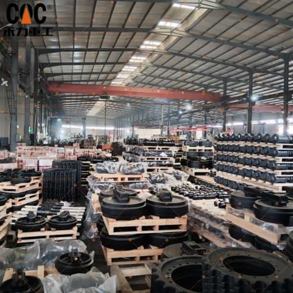
9. Supply Chain Advantages: Direct Factory Sourcing
9.1 Manufacturer Direct Model
The buyer works directly with CQC TRACK (Heli Machinery Manufacturing Co., Ltd.), a primary manufacturer of undercarriage components that supplies both OEM lines and high-grade aftermarket parts. This direct supply model eliminates intermediate traders, reducing per-unit cost while simultaneously improving communication clarity and supply chain predictability.
The manufacturer maintains production capabilities for a complete range of undercarriage components for excavators and bulldozers from multiple major brands, including Komatsu, Caterpillar, Hitachi, and Liebherr. This breadth of production experience directly benefits XCMG part production, as the same manufacturing engineering resources apply comparable process controls across all product lines.
9.2 Custom Manufacturing Capability
For aftermarket clients with specific requirements, CQC TRACK offers OEM and custom manufacturing services. Buyers may provide drawings or physical samples, and the engineering team will produce components to those specifications. This capability is particularly relevant for customers operating modified machines or seeking material upgrades beyond the standard specification.
9.3 Logistics and Export Capacity
The manufacturer has established logistics partnerships supporting shipments to North America, Europe, Africa, and Southeast Asia. Order lead times typically range from 15 to 30 days, depending on quantity and current production scheduling. Bulk order pricing is available to volume buyers. For distributors and dealers, the supplier offers ongoing supply agreements with guaranteed pricing and delivery windows, enabling predictable parts inventory management.
10. Technical Specifications Summary
| Parameter | Specification |
|---|---|
| OEM Part Number | 414102203 |
| Component Type | Track Bottom Roller Assembly (Sealed & Lubricated) |
| Host Machine Model | XCMG XE335C Hydraulic Excavator |
| Machine Operating Weight | 33,800 kg |
| Flange Configuration | Double-flange, integral forged |
| Roller Shell Material | Forged micro-alloyed boron steel (40Mn2/50Mn) |
| Shaft Material | Quenched & tempered alloy steel (42CrMo class) |
| Bearing Type | Tin-bronze bushing, pressed fit |
| Sealing Type | Double floating oil seals (high-chromium alloy + O-ring) |
| Seal Installation Force | 450–500 N per seal pair |
| Running Surface Hardness | HRC 48–55 |
| Hardened Case Depth | 5–8 mm |
| Shaft Surface Hardness | HRC 48–55 |
| Shaft Core Hardness | ≥ HRC 28 |
| Axial Clearance (post-assembly) | 0.4–0.9 mm |
| Quality Certifications | ISO 9001:2015; CQC Product Certification |
| Manufacturer | Heli Machinery Manufacturing Co., Ltd. (CQC TRACK) |
| Supply Model | Factory-direct, manufacturer source |
11. Conclusion
The XCMG XE335C 414102203 Track Bottom Roller Assembly from CQC TRACK represents an OEM-quality undercarriage replacement component manufactured with rigorous process control, advanced metallurgy, and direct factory supply economics. For fleet managers and procurement specialists optimizing their XCMG excavator parts strategy, this assembly delivers documented performance characteristics matched to the 33.8-ton machine platform, with extended hardened case depth, double-floating-seal contamination protection, and dual-layer quality assurance through both ISO system certification and CQC product certification.
The manufacturer‘s direct sourcing model provides a supply chain advantage over multi-tiered distribution channels, supporting both single-unit replacement orders for individual machines and volume stocking arrangements for distributors. With established logistics to major global markets, custom manufacturing capability, and competitive lead times, CQC TRACK positions this assembly as a technically robust and economically efficient alternative within the crawler excavator undercarriage aftermarket.
Products categories
-

LIUGONG 51C0331 CLG933E Track Bottom Roller Ass...
-

CAT 6095428 MD6250 Track Lower Roller Group | H...
-

KATO 54750800110 70750800110 73750800101 HD700 ...
-

Hitachi 9066690 9114619 9114682 9249808 9253782...
-

KOBELCO 24100N7039F3KR 24100n7039F3 SK480 SK500...
-

CATERPILLAR 6Y1824 CR6378 1091215 1373369 15241...


