
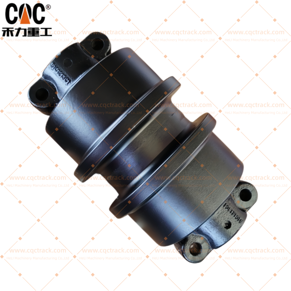
LIUGONG 51c1213 51c1213c1 CLG965 Track Upper Roller Assembly / Track Carrier Roller Group / OEM And ODM Undercarriage Parts Source manufacturer and Supplier / CQC Track


Comprehensive Technical Analysis: LIUGONG 51C1213 / 51C1213C1 CLG965 Track Upper Roller Assembly – OEM and ODM Undercarriage Parts Source Manufacturer and Supplier – CQC TRACK
Executive Summary
This technical publication delivers an exhaustive examination of the LIUGONG 51C1213 and 51C1213C1 track upper roller assembly (alternatively designated as carrier roller group) — a mission-critical undercarriage component engineered for the CLG965 heavy-duty crawler excavator. The CLG965 represents Liugong’s advanced large-class excavator in the 60-65 ton range, deployed in demanding applications including large-scale quarry operations, major infrastructure development, heavy construction, and mining support activities worldwide.
The upper roller assembly serves the essential function of supporting the upper run of the track chain between the front idler and rear sprocket, preventing excessive track sag and maintaining proper engagement with the drive system. For operators of Liugong’s 60-ton class excavators, understanding the engineering principles, material specifications, and manufacturing quality indicators of this component is essential for making informed procurement decisions that optimize total cost of ownership in demanding applications.
This analysis examines the LIUGONG carrier roller through multiple technical lenses: functional anatomy, metallurgical composition for heavy-duty applications, advanced manufacturing process engineering, rigorous quality assurance protocols, and strategic sourcing considerations—with particular focus on CQC TRACK (HELI MACHINERY MANUFACTURING CO., LTD.) as a specialized OEM and ODM source manufacturer of heavy-duty crawler excavator undercarriage parts based in Quanzhou, China, recognized as one of the top three manufacturers in the region with over 20 years of manufacturing experience and ISO 9001:2015 certification .
1. Product Identification and Technical Specifications
1.1 Component Nomenclature and Application
The LIUGONG 51C1213 / 51C1213C1 track upper roller assembly is an OEM-specified undercarriage component engineered specifically for the CLG965 heavy-duty excavator. The part numbers 51C1213 and 51C1213C1 represent Liugong’s proprietary identification codes, with the “C1″ suffix typically indicating a revised or enhanced variant reflecting engineering improvements over the original design. These correspond to precise engineering drawings, dimensional tolerances, and material specifications developed through the original equipment manufacturer’s rigorous validation protocols.
This upper roller assembly is compatible with the following Liugong heavy-duty excavator model:
| Model | Operating Weight Range | Engine Power | Machine Class | Typical Applications |
|---|---|---|---|---|
| CLG965 | 60-65 tons | 320-350 kW | Large construction / heavy quarry | Infrastructure, quarry, heavy earthmoving |
The CLG965 represents Liugong’s advanced large-class excavator, featuring robust undercarriage design optimized for demanding applications including:
- Large-scale quarry operations: Material handling, secondary breaking, stockpile management
- Major infrastructure projects: Highway construction, dam development, site preparation
- Heavy construction: Mass excavation for industrial and commercial developments
- Mining support: Overburden removal, utility work in mining environments
1.2 Primary Functional Responsibilities
The upper roller assembly in 60-ton class excavator applications performs three interconnected functions critical to machine performance and undercarriage longevity:
Track Chain Support: The carrier roller’s peripheral surface contacts the upper run of the track chain, supporting its weight between the front idler and rear sprocket. For 60-65 ton class machines with track chains weighing 200-300 kg per meter, the carrier rollers must support substantial static loads (typically 800-1,200 kg per roller) while accommodating dynamic loading during machine operation. The CLG965 undercarriage typically incorporates 2-3 carrier rollers per side, strategically positioned to maintain optimal chain support throughout the track trajectory .
Chain Guidance: The roller maintains proper chain alignment, preventing lateral displacement that could cause the chain to contact the track frame or other undercarriage components. This guidance function is particularly critical during machine turning and operation on side slopes up to 30° in quarry applications. Upper rollers for these machines feature robust double-flange configurations that provide positive track retention in both directions, essential for maintaining stability on uneven terrain .
Shock Load Management: During travel over uneven terrain, the carrier roller absorbs impact loads transmitted through the track chain, protecting the track frame and final drive from shock-induced damage. The roller’s engineering incorporates both exceptional structural strength and controlled deflection characteristics to manage these dynamic loads without compromising bearing integrity or seal performance .
1.3 Technical Specifications and Dimensional Parameters
While Liugong’s exact engineering drawings remain proprietary, industry-standard specifications for 60-ton class excavator carrier rollers typically encompass the following parameters based on established manufacturing standards and CQC TRACK’s engineering capabilities :
| Parameter | Typical Specification Range | CQC TRACK Achievement | Engineering Significance |
|---|---|---|---|
| Outer Diameter | 350-420 mm | ±0.10 mm tolerance | Determines contact radius with track chain and rolling resistance |
| Shaft Diameter | 90-110 mm | h6 tolerance (±0.015-0.025 mm) | Shear and bending capacity under combined loads |
| Roller Width | 130-170 mm | ±0.15 mm | Contact surface area with track chain rail |
| Flange Configuration | Double-flange design | Precision-machined | Positive track retention for side-slope operation |
| Flange Height | 24-30 mm | Controlled profile | Lateral stability and anti-derailment protection |
| Flange Width | 110-150 mm | ±0.15 mm | Lateral constraint effectiveness |
| Mounting Configuration | Heavy-duty shaft mount with bracket | Forged construction | Secure attachment to track frame |
| Assembly Weight | 80-140 kg | Verified | Material content and structural robustness indicator |
| Bearing Configuration | Matched heavy-duty tapered roller bearings | Premium source (Timken®/equivalent) | Accommodates combined radial and thrust loads |
| Material Specification | SAE 4140 / 42CrMo / 50Mn premium alloy steel | Certified alloy | Optimal balance of hardness and toughness for heavy duty |
| Core Hardness | 280-350 HB (29-38 HRC) | 100% verified | Toughness for impact absorption |
| Surface Hardness | HRC 58-62 | Induction hardened | Wear resistance for extended service life |
| Hardened Case Depth | 8-12 mm | Controlled gradient | Depth of wear-resistant layer for heavy-duty cycles |
| Tread Runout | ≤0.15 mm TIR | CMM verified | Vibration and track chain impact prevention |
| Concentricity | ≤0.10 mm | CMM verified | Smooth rotation and even wear distribution |
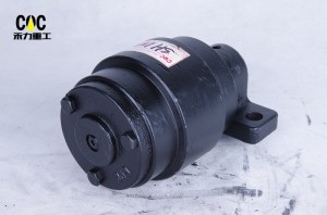
1.4 Component Anatomy and Design Architecture
The upper roller assembly for Liugong CLG965 comprises several key components engineered for heavy-duty operation:
Roller Shell (Body): The outer cylindrical component that makes direct contact with the track chain links. Manufactured from high-carbon, high-strength forged alloy steel, the outer surface is precision-machined and undergoes induction hardening to achieve high surface hardness for extreme abrasion resistance, while the core remains tough to absorb impacts .
Outer Rim Configuration: The outer rim features a precisely contoured tread surface with optimized crown profile (typically 1.0-1.5 mm radius) to accommodate minor track misalignment and prevent edge loading. The dual-flange configuration provides positive track retention in both directions, essential for operation on side slopes up to 30°. The flanges are integral, massive double flanges machined onto both ends of the roller shell, serving as crucial guiding elements to prevent lateral derailment .
Shaft (Spindle or Journal): The stationary axle manufactured from high-strength alloy steel (typically 40Cr or 42CrMo) with precision-ground bearing journals (h6 tolerance) and surface treatments for enhanced durability. The shaft undergoes quenching and tempering heat treatment, giving it a tough, ductile core with high yield strength to resist bending and fatigue fracture .
Bearing System: Matched sets of heavy-duty tapered roller bearings pressed into each end of the roller shell. These bearings are specifically selected to handle the immense radial loads generated by the machine’s weight and operational forces. The self-aligning capability accommodates minor misalignments between the shaft and support brackets, preventing binding and premature bearing failure .
Sealing System: A multi-stage, positive-action seal system critical for longevity. This typically consists of:
| Seal Component | Function | Engineering Significance |
|---|---|---|
| Primary Lip Seal | Prevents escape of lubricating grease from bearing cavity | Retains lubricant for bearing life |
| Secondary Dust Lip | Excludes abrasive contaminants (dirt, mud, sand, water) | Protects against primary failure mode |
| Labyrinth Configuration | Creates tortuous path for contaminant ingress | First line of defense against coarse debris |
| Metal Seal Case | Provides rigid, press-fit housing for seals | Ensures secure fit and heat dissipation |
Modern assemblies, including those from CQC TRACK, are Lube-for-Life designs, meaning they are sealed, pre-greased at the factory with high-quality EP (extreme pressure) lithium complex grease, and require no routine maintenance greasing during service life .
Mounting Interface: The assembly incorporates precision-machined mounting bosses at each end of the shaft, featuring precisely drilled holes for the mounting bolts that secure the entire assembly to the track frame. Proper bolt torque integrity is essential to prevent catastrophic structural failure .
2. Metallurgical Foundation: Material Science for Heavy-Duty Excavator Applications
2.1 Premium Alloy Steel Selection Criteria
The service environment of a 60-ton class excavator upper roller presents demanding material requirements. The component must simultaneously :
- Resist abrasive wear from continuous contact with the track chain and exposure to soil, sand, rock, and construction debris
- Withstand impact loads from machine travel over rough terrain and dynamic loading during operation
- Maintain structural integrity under cyclic loading exceeding 10⁷ cycles over the machine’s lifetime
- Preserve dimensional stability despite exposure to temperature extremes (-30°C to +50°C), moisture, and chemical contaminants
Premium manufacturers like CQC TRACK select specific premium alloy steel grades that achieve the optimal balance of hardness, toughness, and fatigue resistance for heavy-duty excavator applications :
SAE 4140 / 42CrMo Chromium-Molybdenum Alloy: This is the preferred material for demanding carrier rollers. With carbon content of 0.38-0.45%, chromium of 0.90-1.20%, and molybdenum of 0.15-0.25%, SAE 4140 provides:
| Property | Typical Value | Engineering Significance |
|---|---|---|
| Ultimate Tensile Strength | 850-1000 MPa | Load-carrying capacity under extreme stress |
| Yield Strength | 700-850 MPa | Resistance to permanent deformation |
| Elongation | 12-16% | Ductility for impact absorption |
| Reduction of Area | 45-55% | Material quality indicator |
| Hardness (Q&T) | 280-350 HB | Core toughness for impact resistance |
| Impact Toughness | 40-60 J | Low-temperature performance |
50Mn / 55Mn Manganese Steel: For applications where enhanced wear resistance is prioritized, 50Mn with carbon 0.45-0.55% and manganese 1.4-1.8% provides :
- Excellent surface hardenability (critical for large-diameter rollers)
- Good wear resistance from carbide formation
- Adequate toughness for most heavy-duty applications
- Boron micro-alloyed variants for enhanced hardenability
Material Traceability: Reputable manufacturers provide comprehensive material documentation, including Mill Test Reports (MTRs) certifying chemical composition with element-specific analysis (C, Si, Mn, P, S, Cr, Mo, Ni as applicable). Spectrographic analysis confirms alloy chemistry against certified specifications at raw material receipt .
2.2 Forging vs. Casting: The Grain Structure Imperative
The primary forming method fundamentally determines the carrier roller’s mechanical properties and service life. While casting offers cost advantages for simple geometries, it produces an equiaxed grain structure with random orientation, potential porosity, and inferior impact resistance. Premium excavator carrier roller manufacturers exclusively employ closed-die hot forging for the roller body .
The forging process for CLG965 class components begins with cutting steel billets to precise weight, heating them to approximately 1150-1250°C until fully austenitized, then subjecting them to high-pressure deformation between precision-machined dies in hydraulic presses. This thermo-mechanical treatment produces continuous grain flow that follows the component contour, aligning grain boundaries perpendicular to principal stress directions. The resulting structure exhibits :
| Property Improvement | Forged vs. Cast | Engineering Benefit |
|---|---|---|
| Fatigue Strength | +20-30% | Longer service life under cyclic loading |
| Impact Energy Absorption | +30-40% | Better resistance to shock loads |
| Structural Integrity | No porosity/inclusions | Elimination of failure initiation sites |
| Grain Orientation | Aligned with stress | Optimized load distribution |
| Density | 100% theoretical | Maximum material strength |
After forging, components undergo controlled cooling to prevent the formation of detrimental microstructures such as Widmanstätten ferrite or excessive grain boundary carbide precipitation.
2.3 Dual-Property Heat Treatment Engineering for Heavy-Duty Components
The metallurgical sophistication of a quality heavy-duty carrier roller manifests in its precisely engineered hardness profile—an extremely hard, wear-resistant surface coupled with a tough, impact-absorbing core :
Quenching and Tempering (Q&T) : The entire forged roller body is austenitized at 840-880°C, then rapidly quenched in agitated water, oil, or polymer solution. This transformation produces martensite—providing maximum hardness but with associated brittleness. Immediate tempering at 500-650°C allows carbon to precipitate as fine carbides, relieving internal stresses and restoring toughness. The resulting core hardness typically ranges from 280-350 HB (29-38 HRC), providing optimal toughness for impact absorption.
Induction Surface Hardening: Following finish machining, the critical wear surfaces—specifically the tread diameter and flange faces—undergo localized induction hardening. A precision-designed multi-turn copper inductor coil surrounds the component, inducing eddy currents that rapidly heat the surface layer to austenitizing temperature (900-950°C) within seconds. Immediate water quenching produces a martensitic case of 8-12 mm depth with surface hardness of HRC 58-62, providing exceptional resistance to abrasive wear .
Hardness Profile Verification: Quality manufacturers perform microhardness traverses on sample components to verify case depth compliance. A typical hardness profile shows :
| Depth from Surface | Hardness Range | Microstructure |
|---|---|---|
| 0-2 mm | HRC 58-62 | Tempered martensite |
| 2-4 mm | HRC 55-58 | Tempered martensite |
| 4-6 mm | HRC 50-55 | Tempered martensite/bainite |
| 6-8 mm | HRC 45-50 | Bainite/martensite |
| Core (>8 mm) | 280-350 HB | Tempered martensite/bainite |
2.4 Comprehensive Quality Assurance Protocols
Manufacturers like CQC TRACK implement multi-stage quality verification throughout production, with protocols aligned to CQC factory quality assurance requirements :
- Spectroscopic Material Analysis: Confirms alloy chemistry against certified specifications at raw material receipt
- Ultrasonic Testing (UT) : Inspection of critical forgings verifies internal soundness, detecting any centerline porosity or inclusions
- Hardness Verification: Rockwell or Brinell hardness testing confirms both core and surface hardness; enhanced sampling rates for critical features
- Magnetic Particle Inspection (MPI) : Examines critical areas—particularly flange roots and shaft transitions—detecting surface-breaking cracks
- Dimensional Verification: Coordinate Measuring Machines (CMM) verify critical dimensions, maintaining process capability indices (Cpk) exceeding 1.33
- Running Test Validation: Assembled carrier rollers undergo rotational torque and seal integrity testing to verify performance before shipment
3. Precision Engineering: Component Design and Manufacturing
3.1 Roller Geometry Optimization
The carrier roller geometry for CLG965 class machines must precisely match the track chain specifications while accommodating operational loads :
Outer Diameter: The 350-420 mm diameter is calculated to provide appropriate rotational speed and bearing L10 life at typical travel speeds. The diameter must be maintained within tight tolerances (±0.10 mm) to ensure consistent chain support height.
Tread Profile Design: The contact surface incorporates an optimized crown profile (typically 1.0-1.5 mm radius) to accommodate minor track misalignment and prevent edge loading. Key design parameters include :
| Tread Parameter | Specification | Engineering Significance |
|---|---|---|
| Crown Radius | 1.0-1.5 mm | Accommodates misalignment, prevents edge loading |
| Surface Roughness (Ra) | ≤1.6 µm | Optimizes wear characteristics |
| Profile Tolerance | ±0.10 mm | Ensures consistent chain engagement |
Flange Configuration: Carrier rollers feature robust double-flange designs providing positive track retention in both directions. Critical flange design elements include :
| Flange Feature | Specification | Engineering Significance |
|---|---|---|
| Flange Height | 24-30 mm | Provides robust lateral constraint |
| Flange Width | 110-150 mm | Ensures adequate strength |
| Flange Face Relief Angle | 8-12° | Facilitates debris ejection |
| Flange Root Radius | 8-12 mm | Minimizes stress concentration |
| Flange Face Hardness | HRC 58-62 | Wear resistance |
3.2 Shaft and Bearing System Engineering
The stationary shaft must withstand continuous bending moments and shear stresses. For CLG965 applications, shaft diameters typically range 90-110 mm, calculated based on :
- Static machine weight distributed to each carrier roller
- Dynamic load factors of 2.5-3.5 for heavy-duty applications
- Track tension loads transmitted through the chain
- Side loads during turning and slope operation
The bearing system employs matched sets of heavy-duty tapered roller bearings :
| Bearing Parameter | Specification | Engineering Significance |
|---|---|---|
| Bearing Type | Matched tapered roller bearings | Simultaneously supports radial and thrust loads |
| Dynamic Load Rating (C) | 400-700 kN | Appropriate for 60-65 ton class |
| Cage Design | Machined brass cage | Superior shock load resistance |
| Internal Clearance | C3 or C4 class | Accommodates thermal expansion |
3.3 Advanced Multi-Stage Sealing Technology
The seal system is the single most critical determinant of carrier roller longevity. Premium heavy-duty carrier rollers employ multi-stage sealing systems :
Primary Heavy-Duty Floating Seal: Precision-ground hardened steel rings with lapped sealing faces achieving flatness within 0.5-1.0 µm, providing exceptional wear resistance in high-contamination environments.
Secondary Radial Lip Seal: Manufactured from HNBR (Hydrogenated Nitrile Butadiene Rubber) with exceptional temperature resistance (-40°C to +150°C), chemical compatibility with EP greases, and enhanced abrasion resistance.
External Labyrinth-Style Dust Guard: Creates a tortuous path with multiple chambers that progressively trap coarse contaminants before they reach the primary seals.
Pre-Lubrication: The bearing cavity is pre-filled with lithium complex, extreme-pressure (EP) grease containing molybdenum disulfide for boundary lubrication, enhanced anti-wear additives, and oxidation stabilizers for extended service intervals.
3.4 Precision Machining and Quality Control
Modern CNC machining centers achieve dimensional tolerances that directly correlate with service life. Critical parameters include :
| Feature | Typical Tolerance | Consequence of Deviation |
|---|---|---|
| Shaft Journal Diameter | h6 to h7 (±0.015-0.025 mm) | Clearance affects lubrication film and load distribution |
| Bearing Bore Diameter | H7 to H8 (±0.020-0.035 mm) | Fit with bearing outer race |
| Seal Housing Bore | H8 to H9 (±0.025-0.045 mm) | Seal compression affects sealing force |
| Tread Runout | ≤0.15 mm TIR | Vibration and track chain impact |
| Surface Finish (seal areas) | Ra ≤0.4 µm | Seal wear rate and leakage prevention |
3.5 Assembly and Pre-Delivery Testing
Final assembly is performed in controlled conditions to prevent contamination. Assembly protocols include :
- Component Cleaning: Thorough cleaning of all components before assembly
- Controlled Environment: Clean assembly areas with contamination control
- Bearing Installation: Precision pressing with force monitoring
- Preload Setting: Tapered roller bearings adjusted to specified preload
- Seal Installation: Specialized tools prevent damage to sealing surfaces
- Lubrication: Measured grease fill with specified lubricants
Pre-delivery testing includes :
- Rotational torque test to verify smooth rotation
- Seal integrity test with pressurized air to detect leakage
- Dimensional inspection of the assembled unit
- Running test on sample basis to verify performance
4. CQC TRACK: OEM and ODM Source Manufacturer Profile
4.1 Company Overview and Strategic Positioning
CQC TRACK (HELI MACHINERY MANUFACTURING CO., LTD.) is a specialized industrial manufacturer and supplier of heavy-duty undercarriage systems and chassis components, operating on both ODM and OEM principles . Founded in the late 1990s, the company has systematically evolved into one of the top three undercarriage component manufacturers in the Quanzhou region, a premier industrial cluster for global earthmoving equipment .
Over 20 Years of Manufacturing Experience: With more than two decades of specialized focus on undercarriage components, CQC TRACK has cultivated deep technical expertise in metallurgy and tribology specific to track systems. This accumulated experience enables the company to deliver components that meet or exceed OEM performance standards .
OEM and ODM Service Model :
- OEM Manufacturing: Produces components to exact client specifications, drawings, and quality standards, integrating seamlessly into global supply chains
- ODM Engineering: Leverages extensive field experience to develop, design, and validate improved or fully customized undercarriage solutions, proactively addressing common failure modes through a “Failure-Mode-Driven” approach
4.2 Core Manufacturing Capabilities and Technological Infrastructure
CQC TRACK’s manufacturing prowess is built on complete vertical integration and controlled, sequential processes :
Integrated Production Workflow:
- In-House Forging: Utilizes premium 52Mn, 55Mn, and 40CrNiMo alloy steels, ensuring optimal grain flow and material density
- CNC Machining Centers: Modern CNC lathes, milling machines, and drilling centers ensuring dimensional accuracy to ISO 2768-mK standards
- Advanced Heat Treatment Lines: Computer-controlled induction hardening and tempering furnaces achieving deep, uniform case hardness (58-63 HRC) with tough ductile core
- Precision Grinding & Finishing: Critical wear surfaces undergo precision grinding to achieve superior surface finish and exact tolerances
- Automated Assembly & Sealing: Clean assembly lines ensuring proper installation of seals, bearings, and lubricants; multi-labyrinth seal configurations as standard
- Surface Protection: Shot-peening for stress relief and high-bond, corrosion-resistant coatings
Quality Assurance & Laboratory Facilities:
| Testing Capability | Equipment | Application |
|---|---|---|
| Material Analysis | Spectrometer | Raw material chemistry verification |
| Hardness & Depth Testing | Rockwell/Brinell testers | Core and surface hardness verification |
| Non-Destructive Testing (NDT) | MPI, UT equipment | Subsurface flaw detection |
| Dimensional Inspection | CMM, precision gauges | Critical feature verification |
| Performance Testing | Custom test rigs | Rotational torque, seal integrity |
Certifications:
- ISO 9001:2015 Certified Quality Management System: Ensuring process discipline, continuous improvement, and documented procedures throughout all manufacturing operations
- CQC Product Certification: Multiple specific CQC product certificates (e.g., CQC17704176145) mandating factory quality assurance systems encompassing supplier vetting, key component validation, and comprehensive record-keeping
- Full Traceability: Complete material and process traceability from forging to final assembly for every production batch
4.3 Engineering Design Philosophy
CQC TRACK’s ODM development follows a “Failure-Mode-Driven” approach :
- Problem Identification: Analyze returned parts from the field to identify root causes (e.g., seal lip wear-out, spalling, abnormal flange wear)
- Solution Integration: Redesign specific features—such as seal groove geometry, grease cavity volume, or flange profile—to mitigate these failures
- Validation: Prototype testing ensures design improvement delivers measurable life extension before mass production
This engineering methodology enables continuous improvement based on real-world performance data from construction and quarry operations worldwide .
4.4 Global Supply Chain and Customer Value Proposition
Supply Chain Reliability:
- Strategic Location: Based in Quanzhou with efficient access to major ports (Xiamen, Quanzhou), facilitating reliable global logistics
- Inventory Management: Support for both bulk orders and flexible JIT delivery programs
- Packaging: Export-standard, weather-resistant packaging on solid wooden pallets ensuring product integrity during transit
- Documentation: Comprehensive shipping docs including material test certificates and factory inspection reports
Value Delivered to Partners:
- Superior Total Cost of Ownership (TCO) : Extended service life through superior materials and hardening, reducing machine downtime
- Technical Partnership: Engineering support for specific application challenges
- Supply Chain Simplification: Factory-direct source with full manufacturing control, providing consistency and transparency
5. CLG965 Undercarriage System Integration
5.1 Undercarriage System Context
The CLG965 undercarriage system represents robust track design for heavy-duty applications :
| Component | Typical Specification | Features |
|---|---|---|
| Track Chain Pitch | 190-216 mm | Sealed and lubricated design |
| Track Shoe Width | 600-800 mm | Multiple widths for ground pressure optimization |
| Number of Track Rollers | 7-9 per side | Sealed rollers with dual-flange configuration |
| Number of Carrier Rollers | 2-3 per side | Upper rollers with enhanced seals |
| Track Gauge | 2,500-2,800 mm | Wide stance for stability |
The upper roller assembly works in conjunction with the drive sprocket at the rear, front idler, and track rollers to form a complete, balanced undercarriage system. Its position relative to the sprocket and idler helps define the contact length of the track on the ground, directly impacting ground pressure, stability, and traction .
5.2 Integration with Track Tensioning System
The upper roller assembly interfaces with the track tensioning mechanism through its effect on track sag. Proper track tension, typically measured as sag (e.g., 30-50 mm) at the midpoint between the front idler and the first carrier roller, is vital for optimal undercarriage life. Incorrect tension is a primary cause of premature wear across all undercarriage components .
5.3 Performance Optimization
The upper roller’s condition directly impacts the entire undercarriage system. When operating with balanced, properly maintained carrier rollers, the machine benefits from :
- Reduced dynamic loading on the track chain
- Even distribution of wear across all undercarriage components
- Improved stability during side-slope operation
- Extended service life for the entire undercarriage system
6. Performance Validation and Service Life Expectations
6.1 Benchmarks for 60-65 Ton Class Excavator Carrier Rollers
Field data from diverse operating environments provides realistic performance expectations :
| Application Severity | Operating Environment | Expected Service Life |
|---|---|---|
| General Construction | Mixed terrain, moderate conditions | 5,000-7,000 hours |
| Heavy Construction | Major earthmoving, varied terrain | 4,500-6,000 hours |
| Quarry Operations | Continuous operation, moderate abrasion | 4,000-5,500 hours |
| Infrastructure | Highway/development projects | 4,500-6,500 hours |
Premium aftermarket carrier rollers from reputable manufacturers like CQC TRACK demonstrate performance parity with OEM heavy-duty components, achieving 85-95% of OEM service life at significantly lower acquisition cost (typically 30-50% below OEM pricing) .
6.2 Common Failure Modes
Understanding failure mechanisms enables proactive maintenance :
Seal Failure and Contamination Ingress: The predominant failure mode, seal compromise allows abrasive particles to enter the bearing cavity. Initial symptoms include grease leakage, increasing operating temperature, rough rotation, and eventually seizure.
Flange Wear: Progressive wear on flange faces indicates inadequate surface hardness or improper track alignment. Critical wear indicators include thinning of flange width and development of sharp edges.
Tread Wear and Diameter Reduction: The roller tread gradually wears from continuous contact. When diameter reduction exceeds specifications (typically 10-15 mm), consequences include altered engagement geometry and increased dynamic loading.
Bearing Fatigue: After extended service, bearings may exhibit spalling due to subsurface fatigue, indicating the component has reached its natural life limit.
Roller Sticking: A flat side on the roller indicates it is stuck, usually caused by sand and/or mud packing between the roller and the undercarriage frame .
6.3 Wear Indicators and Inspection Protocols
Regular inspection at 250-hour intervals should check for :
- Seal condition: Grease leakage, debris accumulation, seal damage
- Roller rotation: Smoothness, noise, binding, rotational resistance
- Operating temperature: Comparison with baseline using infrared thermometer
- Flange condition: Wear measurement, sharp edges, damage, cracks
- Tread condition: Wear pattern analysis, diameter measurement
- Mounting integrity: Fastener torque, bracket condition, alignment
- Visual damage: Cracks, deep gouges, scoring on roller shell
- Leakage: Any signs of grease leaking from seal area
- Unusual noises: Grinding, squeaking, knocking during operation
7. Installation, Maintenance, and Service Life Optimization
7.1 Professional Installation Practices
Proper installation significantly impacts carrier roller service life :
Track Frame Preparation: Mounting surfaces must be clean, flat, and free of burrs, corrosion, or damage. Inspection for cracks or damage around mounting areas is essential.
Bracket Inspection: Mounting brackets should be inspected for wear, crack initiation, corrosion damage, and thread condition.
Fastener Specifications: All mounting bolts must be Grade 10.9 or 12.9 as specified, tightened in proper sequence to specified torque using calibrated torque wrenches, and equipped with appropriate locking features. Retorquing after initial operation (typically 50-100 hours) is recommended.
Alignment Verification: After installation, verify that the roller is properly aligned with the track chain path, contacts the track chain evenly across its width, and rotates freely without binding.
Track Tension Adjustment: After installation, verify proper track tension according to machine specifications. For 60-ton class excavators, proper sag typically ranges 30-50 mm .
7.2 Preventive Maintenance Protocols
Regular Inspection Intervals: Visual inspection at 250-hour intervals should check for all wear indicators previously described. Daily walk-around should include visual check for obvious seal leakage or damage.
Track Tension Management: Check tension at every 250-hour service interval, after new component installation, when operating conditions change, and when abnormal track behavior is observed.
Cleaning Protocols: Regular cleaning is essential but must be performed correctly. Avoid high-pressure washing directed at seal areas. Use low-pressure water for general cleaning. Remove accumulated debris from around rollers during daily inspections .
Lubrication: For carrier rollers with sealed bearings (Lube-for-Life designs), no additional lubrication is required during service life .
Operating Practice Considerations: Minimize high-speed travel over rough terrain, avoid sudden direction changes, keep track tension properly adjusted, and report unusual noises or handling immediately.
7.3 Replacement Decision Criteria
Carrier rollers should be replaced when :
- Seal leakage is evident and cannot be stopped
- Radial play exceeds manufacturer specifications (typically 3-5 mm)
- Flange wear reduces guidance effectiveness (thickness reduction exceeding 25%)
- Flange damage includes cracks, spalling, or severe deformation
- Tread wear exceeds hardened case depth (diameter reduction exceeding 10-15 mm)
- Surface spalling affects more than 10% of contact area
- Bearing rotation becomes rough, noisy, or irregular
- Roller is stuck (flat side visible) due to contamination
- Visible damage includes cracks, impact damage, or deformation
7.4 System-Based Replacement Strategy
For optimal undercarriage performance, the carrier roller condition should be evaluated alongside :
- Track chain (pin and bushing wear, rail condition)
- Track rollers (bottom)
- Front idler
- Sprocket
- Track frame alignment
Industry best practice recommends :
- Replace in pairs: Carrier rollers on both sides together to maintain balanced performance
- Consider system replacement: When multiple components show significant wear
- Schedule during major service: Plan during scheduled downtime
8. Strategic Sourcing Considerations
8.1 The OEM vs. Aftermarket Decision
Equipment managers must evaluate the OEM versus high-quality aftermarket decision through multiple lenses:
Cost Analysis: Aftermarket components typically offer 30-50% initial cost savings compared to OEM parts. Total cost of ownership calculations must factor in expected service life, maintenance labor costs, downtime impact, warranty coverage, and parts availability.
Quality Parity: Premium aftermarket manufacturers achieve performance parity with OEM components through :
- Equivalent material specifications (SAE 4140/50Mn with certified chemistry)
- Comparable heat treatment processes (core 280-350 HB, surface HRC 58-62, case depth 8-12 mm)
- Heavy-duty sealing systems with multi-stage contamination protection
- Matched bearing sets from reputable manufacturers
- Rigorous quality control with comprehensive testing
- ISO 9001:2015 certified quality management systems
Warranty Considerations: Reputable aftermarket manufacturers offer comparable warranties covering manufacturing defects, with coverage periods appropriate for heavy-duty applications.
Availability and Lead Times: Aftermarket manufacturers often deliver within 4-8 weeks, with emergency expediting available for critical situations—essential for minimizing downtime.
8.2 Supplier Evaluation Criteria
Procurement professionals should apply rigorous evaluation frameworks :
Manufacturing Capability Assessment: Verify presence of forging equipment, CNC machining centers, heat treatment facilities, induction hardening stations, clean assembly areas, and comprehensive testing facilities (UT, MPI, CMM, metallurgical laboratory).
Quality Management Systems: ISO 9001:2015 certification represents the minimum acceptable standard. CQC product certification demonstrates enhanced commitment to quality.
Material and Process Transparency: Reputable manufacturers readily provide material certifications (MTRs), heat treatment documentation, inspection reports, and sample testing capability.
Experience and Reputation: Suppliers with over 20 years of experience in heavy-duty applications demonstrate sustained capability.
8.3 The CQC TRACK Advantage
CQC TRACK offers several distinct advantages for Liugong excavator undercarriage procurement :
- 20+ Years Manufacturing Experience: Deep technical expertise in metallurgy and tribology
- Top Three Quanzhou Manufacturer: Recognized position in China’s premier undercarriage manufacturing cluster
- OEM/ODM Manufacturing Capability: Components engineered to exact specifications with custom design capability
- Integrated Production Control: Full vertical integration ensures consistent quality and traceability
- Material Excellence: Premium SAE 4140/42CrMo alloy steel with surface hardness HRC 58-62, case depth 8-12 mm
- Advanced Sealing: Multi-stage sealing systems with labyrinth-style, multi-lip seals
- Comprehensive Quality Assurance: ISO 9001:2015 certified, CQC product certification, 100% UT inspection
- Global Supply Capability: Reliable lead times from Quanzhou with efficient port access
- Competitive Economics: 30-50% cost savings while maintaining heavy-duty quality
- Engineering Support: Customization capabilities for specific operating conditions
9. Conclusion and Strategic Recommendations
The LIUGONG 51C1213 and 51C1213C1 track upper roller assembly for CLG965 excavators represents a precision-engineered heavy-duty component whose performance directly impacts machine availability, operating cost, and project profitability. Understanding the technical intricacies—from alloy selection (SAE 4140/42CrMo/50Mn) and forging methodology through precision machining, bearing systems, and multi-stage seal design—enables equipment managers to make informed procurement decisions that balance initial cost against total cost of ownership .
For heavy equipment operators utilizing Liugong 60-ton class excavators, the following strategic recommendations emerge :
- Prioritize heavy-duty specifications, verifying material grades (SAE 4140/42CrMo/50Mn), heat treatment parameters (core 280-350 HB, surface HRC 58-62, case depth 8-12 mm), and seal system design for contamination environments .
- Verify sealing system robustness, recognizing that multi-stage seals with labyrinth construction and HNBR lip seals provide essential protection .
- Evaluate suppliers through manufacturing capability lens, seeking evidence of forging capacity, modern CNC equipment, heat treatment capability, and comprehensive testing facilities.
- Demand material and process transparency, requesting material certifications, heat treatment records, and inspection reports.
- Confirm cross-reference accuracy when substituting aftermarket components for OEM part numbers 51C1213 and 51C1213C1, ensuring compatibility with CLG965 model.
- Implement appropriate maintenance protocols, including regular inspection for seal condition, tread wear, and flange integrity, with attention to preventing roller sticking from contamination .
- Adopt system-based replacement strategies, evaluating carrier roller condition alongside track chain, bottom rollers, idler, and sprocket.
- Develop strategic supplier partnerships with manufacturers like CQC TRACK that demonstrate technical competence, quality commitment, and supply chain reliability .
- Consider total cost of ownership, evaluating aftermarket options that offer 30-50% cost savings while maintaining heavy-duty quality.
By applying these principles, equipment operators can secure reliable, cost-effective undercarriage solutions that maintain excavator productivity while optimizing long-term operational economics.
CQC TRACK, as a specialized manufacturer with over 20 years of experience, integrated production capabilities, and comprehensive quality assurance based in Quanzhou, China, represents a viable source for LIUGONG 51C1213 / 51C1213C1 carrier roller assemblies, offering OEM and ODM quality with the cost advantages of specialized Chinese manufacturing .
Frequently Asked Questions (FAQ)
Q: What is the typical service life of a LIUGONG 51C1213 carrier roller on CLG965 excavators?
A: Service life varies with operating conditions: general construction 5,000-7,000 hours, heavy construction 4,500-6,000 hours, quarry operations 4,000-5,500 hours, infrastructure projects 4,500-6,500 hours.
Q: How can I verify that an aftermarket carrier roller meets Liugong specifications?
A: Request material test reports (MTRs) certifying alloy chemistry (SAE 4140/50Mn), hardness verification documentation (core 280-350 HB, surface HRC 58-62, case depth 8-12 mm), and dimensional inspection reports. Reputable manufacturers like CQC TRACK readily provide this documentation .
Q: What is the difference between part numbers 51C1213 and 51C1213C1?
A: The “C1″ suffix typically indicates a revised or enhanced variant of the original 51C1213 design, reflecting engineering improvements over the original specification. Both are compatible with CLG965, with the C1 variant incorporating design refinements.
Q: What distinguishes heavy-duty carrier rollers from standard-grade components?
A: Heavy-duty components feature enhanced material specifications (SAE 4140), increased hardened case depth (8-12 mm), more robust bearing selections, advanced multi-stage sealing systems, and rigorous quality control .
Q: How do I identify seal failure before catastrophic damage occurs?
A: Regular inspection should check for grease leakage around seals (visible as wetness or accumulated debris). Thermographic imaging can identify bearing distress through temperature rise. Rough rotation during maintenance checks also indicates seal compromise .
Q: What causes premature carrier roller wear?
A: Common causes include seal failure allowing contaminant ingress (most common), improper track tension, operation in highly abrasive materials, mixing new rollers with worn track components, and contamination buildup causing roller sticking .
Q: How do I identify a stuck carrier roller?
A: A flat side on the roller indicates that the carrier roller is stuck, usually caused by sand and/or mud between the roller and the undercarriage frame. Regular cleaning helps prevent this condition .
Q: Should I replace carrier rollers individually or in pairs?
A: Industry best practice recommends replacing carrier rollers in pairs on each side to maintain balanced track performance and prevent accelerated wear of new components paired with worn counterparts.
Q: What warranty should I expect from quality aftermarket suppliers?
A: Reputable aftermarket manufacturers like CQC TRACK typically offer 1-2 year warranties covering manufacturing defects, with coverage periods appropriate for heavy-duty applications.
Q: Can aftermarket carrier rollers be customized for specific operating conditions?
A: Yes, experienced manufacturers like CQC TRACK offer customization options including enhanced seal systems for extreme conditions, modified material grades, and geometry adjustments for specialized applications, following a “Failure-Mode-Driven” ODM engineering approach .
Q: What are the critical wear indicators for excavator carrier rollers?
A: Critical wear indicators include seal leakage, reduction in outside diameter (exceeding 10-15 mm), flange wear (thickness reduction exceeding 25%), abnormal radial play (exceeding 3-5 mm), rough rotation, roller sticking (flat side), and visible damage .
Q: How often should track tension be checked on CLG965 excavators?
A: Track tension should be checked at every 250-hour service interval, after new component installation, when operating conditions change, and whenever abnormal track behavior is observed .
Q: What are the advantages of sourcing from CQC TRACK for Liugong excavator components?
A: CQC TRACK offers competitive pricing (30-50% below OEM), over 20 years of manufacturing experience, top-three Quanzhou manufacturer status, heavy-duty manufacturing capability with premium alloys, advanced multi-stage sealing systems, comprehensive quality assurance (ISO 9001:2015 certified, CQC certified), and engineering expertise in Liugong applications .
Q: What maintenance practices extend carrier roller life?
A: Key practices include proper track tension maintenance, regular inspection for seal condition and early leakage detection, regular cleaning to prevent roller sticking, avoidance of high-pressure washing at seals, prompt replacement at wear limits, and system-based replacement strategies .
Q: Where is CQC TRACK located?
A: CQC TRACK is based in Quanzhou, Fujian Province, China—a premier industrial cluster for construction machinery manufacturing with strategic access to major international ports (Xiamen, Quanzhou) for efficient global distribution .
This technical publication is intended for professional equipment managers, procurement specialists, and maintenance personnel in heavy construction and quarry operations. Specifications and recommendations are based on industry standards and manufacturer data available at time of publication. All manufacturer names, part numbers, and model designations are used for identification purposes only. For specific application requirements and current product specifications, please consult CQC TRACK’s engineering team directly .
Products categories
-

VOLVO (14531515 / 71499210 / 4349518 / 9078675 ...
-

SANY 13882679 SY950 SY980 Track Upper Roller / ...
-
Construction Machinery Parts Excavator Carrier ...
-

SUMITOMO CASE KBA1141 VC4143A0 SH300 SH330 SH35...
-

High Quality Roller Ex70 Top Roller Black, Hot ...
-

(200105-00002C/200105-00028)DOOSAN/DX480/500/52...


