
LIUGONG 51C0166 CLG936 Track Front Idler Assembly / OEM Quality Heavy duty excavator undercarriage parts / source factory and manufacturer / CQC TRACK


Comprehensive Technical Analysis: LIUGONG 51C0166 CLG936 Track Front Idler Assembly – OEM-Grade Heavy Duty Excavator Undercarriage Components
Executive Summary
This technical publication delivers an exhaustive examination of the LIUGONG 51C0166 track front idler assembly, a mission‑critical component engineered for the CLG936 hydraulic excavator. As a key element of the “four wheels and one belt” undercarriage system, the front idler (also referred to as the track adjuster idler or simply idler wheel) performs two fundamental functions: it guides the track chain around the front of the machine and serves as the moving anchor for the track tensioning mechanism. Proper idler design, material selection, and manufacturing precision directly influence track alignment, tension maintenance, shock absorption, and overall undercarriage longevity.
For fleet managers, maintenance professionals, and procurement specialists operating LiuGong 36‑ton‑class excavators in diverse global applications—from infrastructure projects in Southeast Asia to mining operations in Africa and construction sites across the Middle East—understanding the engineering principles, material science, and supplier evaluation criteria for this component is essential for optimizing total cost of ownership and minimising unplanned downtime.
This analysis deconstructs the LIUGONG 51C0166 front idler assembly through multiple technical lenses: functional anatomy, metallurgical composition, manufacturing process engineering, quality assurance protocols, and strategic sourcing considerations—with a special focus on China’s specialised manufacturing clusters that have become global leaders in heavy equipment component production. The term CQC TRACK is referenced as an example of a reputable source factory and manufacturer operating within this ecosystem.
1. Product Identification and Technical Specifications
1.1 Component Nomenclature and Application
The LIUGONG 51C0166 Track Front Idler Assembly is an OEM‑specified undercarriage component designed specifically for the CLG936 hydraulic excavator, a 36‑ton‑class machine widely employed in medium to heavy construction, quarry operations, and infrastructure development. The part number 51C0166 corresponds to LiuGong’s proprietary engineering drawings, which define precise dimensional tolerances, material grades, heat treatment parameters, and assembly specifications developed through the original equipment manufacturer’s rigorous validation and field testing.
Within the “four wheels and one belt” (四轮一带) classification—encompassing track rollers, carrier rollers, front idlers, sprockets, and track chain assemblies—the front idler occupies a unique position. It is the only rotating component that is not fixed to the track frame; instead, it is mounted on a sliding yoke that moves longitudinally, enabling track tension adjustment. This dual role of guidance and tensioning imposes complex loading conditions that demand exceptional structural integrity and wear resistance.
1.2 Primary Functional Responsibilities
The front idler assembly fulfils two interdependent functions that are critical to machine stability, track life, and operator safety:
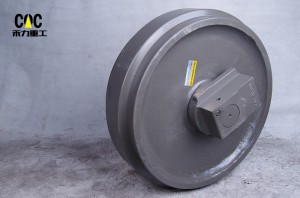
Track Guidance and Load Transfer: The idler’s peripheral surface (the tread) contacts the track chain’s rail section, guiding the chain as it wraps around the front of the machine. During forward travel, the idler experiences compressive forces from the track chain; during reverse travel, it must withstand tensile loads transmitted through the chain. The idler also supports a portion of the machine’s weight, particularly when the excavator is moving forward or when the track is tensioned. The dual‑flange configuration prevents lateral displacement of the track, ensuring proper alignment with the rollers and sprocket.
Track Tensioning Interface: The idler is mounted on a sliding yoke connected to the track adjuster mechanism—typically a hydraulic cylinder with a grease‑filled chamber or a spring‑pack assembly. By moving the idler forward or backward, the mechanic adjusts the track sag, maintaining optimal tension that balances wear reduction (by preventing excessive slack) with mechanical efficiency (by minimising friction and power loss). The idler must therefore accommodate not only rotational motion but also linear translation under high axial loads.
1.3 Technical Specifications and Dimensional Parameters
While LiuGong’s exact engineering drawings are proprietary, industry‑standard specifications for 36‑ton‑class excavator front idlers generally encompass the following parameters:
| Parameter | Typical Specification Range | Engineering Significance |
|---|---|---|
| Outer Diameter | 550‑650 mm | Determines contact radius with track links and influences rolling resistance. |
| Shaft Diameter (bearing bore) | 80‑100 mm | Shear and bending capacity under combined radial and axial loads. |
| Flange Width | 100‑130 mm | Lateral stability and guidance effectiveness, especially during turning. |
| Flange Height | 20‑30 mm | Anti‑derailment protection when operating on side slopes. |
| Sliding Yoke Stroke | 80‑150 mm | Range of track tension adjustment to accommodate wear and operating conditions. |
| Weight (assembly) | 150‑250 kg | Reflects material content and structural robustness. |
| Bearing Type | Tapered roller bearings or heavy‑duty spherical roller bearings | Accommodates combined radial and thrust loads while allowing misalignment. |
These parameters are established through reverse engineering of OEM components or direct collaboration with equipment manufacturers. Premium aftermarket suppliers achieve tolerances of ±0.03 mm on critical bearing journals and seal housing bores, ensuring proper fit and long‑term reliability.
2. Metallurgical Foundation: Material Science for Extreme Durability
2.1 Alloy Steel Selection Criteria
The front idler operates in one of the most demanding mechanical environments in heavy equipment. It must resist abrasive wear from continuous contact with soil, sand, and rock; absorb impact loads from uneven terrain and excavation forces; maintain dimensional stability under cyclic loading that can exceed 10⁷ cycles; and withstand corrosion from moisture, chemicals, and temperature extremes. These requirements dictate the use of specific alloy steel grades that achieve an optimal balance of hardness, toughness, and fatigue resistance.
Premium manufacturers employ medium‑carbon alloy steels with carefully controlled compositions:
50Mn / 40Mn2 Manganese Steel: With carbon content of 0.45‑0.55% and manganese of 1.4‑1.8%, these grades provide excellent hardenability—the ability to achieve uniform hardness at depth during heat treatment. Manganese also enhances tensile strength and wear resistance while maintaining adequate toughness for impact absorption. 50Mn is a common choice for idler wheels in mid‑size excavators.
40Cr / 42CrMo Chromium‑Molybdenum Alloys: For applications demanding enhanced fatigue resistance and through‑hardening capability, chromium‑molybdenum steels such as 40Cr (similar to AISI 5140) or 42CrMo (AISI 4140/4142) are specified. Chromium improves hardenability and provides moderate corrosion resistance; molybdenum refines grain structure and increases high‑temperature strength during heat treatment. These alloys are often used for the sliding yoke and shaft components.
Boron Micro‑Alloyed Steels: Advanced metallurgical practice incorporates boron additions (0.001‑0.003%) to dramatically enhance hardenability. Boron segregates to austenite grain boundaries, retarding transformation to softer microstructures during quenching. This allows full hardness to be achieved at greater section depths, extending the wear‑resistant case deeper into the idler rim.
2.2 Forging vs. Casting: The Grain Structure Imperative
The primary forming method fundamentally determines the idler’s mechanical properties and service life. While casting offers cost advantages for simple geometries, it produces an equiaxed grain structure with random orientation, potential porosity, and inferior impact resistance. Premium front idler manufacturers exclusively employ closed‑die hot forging for the idler wheel (rim and hub) and yoke.
The forging process begins with cutting steel billets to precise weight, heating them to approximately 1150‑1250°C until fully austenitized, then subjecting them to high‑pressure deformation between precision‑machined dies. This thermo‑mechanical treatment produces continuous grain flow that follows the component contour, aligning grain boundaries perpendicular to principal stress directions. The resulting structure exhibits 20‑30% higher fatigue strength and significantly greater impact energy absorption compared to cast alternatives.
After forging, components undergo controlled cooling to prevent the formation of detrimental microstructures such as Widmanstätten ferrite or excessive grain boundary carbide precipitation.
2.3 Dual‑Property Heat Treatment Engineering
The metallurgical sophistication of a quality front idler manifests in its precisely engineered hardness profile—a hard, wear‑resistant surface coupled with a tough, impact‑absorbing core. This “case‑core” composite structure is achieved through a multi‑stage heat treatment regimen:
Quenching and Tempering (Q&T) : The entire forged rim and yoke are austenitized at 840‑880°C, then rapidly quenched in agitated water, oil, or polymer solution. This transformation produces martensite—a supersaturated solid solution of carbon in iron that provides maximum hardness but with associated brittleness. Immediate tempering at 500‑650°C allows carbon to precipitate as fine carbides, relieving internal stresses and restoring toughness while maintaining adequate strength. The resulting core hardness typically ranges from 280‑350 HB (29‑38 HRC), providing optimal toughness for impact absorption.
Induction Surface Hardening: Following finish machining, the critical wear surfaces—specifically the tread diameter and flange faces—undergo localized induction hardening. A copper inductor coil surrounds the component, inducing eddy currents that rapidly heat the surface layer to austenitizing temperature (900‑950°C) within seconds. Immediate water quenching produces a martensitic case of 5‑10 mm depth with surface hardness of 53‑60 HRC.
This precisely controlled differential hardening creates the ideal composite structure: a wear‑resistant rim surface that withstands abrasive contact with track links and ground debris, supported by a tough core that absorbs impact loads without catastrophic fracture.
2.4 Material Certification and Traceability
Reputable manufacturers provide comprehensive material documentation, including Mill Test Reports (MTRs) certifying chemical composition with element‑specific analysis (C, Si, Mn, P, S, Cr, Ni, Mo, Cu, B as applicable). Hardness verification reports document both core and surface hardness values, often with microhardness traverses demonstrating case depth compliance. Ultrasonic inspection confirms internal soundness, while magnetic particle or dye penetrant examination verifies surface integrity.
3. Precision Engineering: Component Design and Manufacturing
3.1 Idler Rim Geometry and Tribological Design
The idler rim geometry must precisely match the track link pitch and rail profile to ensure uniform contact pressure distribution. An incorrectly profiled rim concentrates stress, accelerating localised wear and potentially inducing track jumping. The rim diameter is calculated based on the track pitch and the desired wrap angle around the idler.
Flange geometry is equally critical. The flange‑to‑flange distance must accommodate the track link width with sufficient clearance for free movement while maintaining guidance effectiveness. Flange face angles typically incorporate 5‑10° relief to facilitate debris ejection and prevent material packing that could induce derailment. Flange root radii are optimised to minimise stress concentration while providing adequate strength for anti‑derailment function.
3.2 Shaft and Bearing System Engineering
The front idler rotates on a stationary shaft (or axle) that is mounted within the sliding yoke. The shaft must withstand continuous bending moments and shear stresses while maintaining precise alignment with the rotating rim. Shaft diameters are calculated based on the machine’s static weight, dynamic factors (typically 2.0‑2.5 for excavator applications), and the loads imposed by track tension.
The bearing system is typically one of two configurations:
Tapered Roller Bearings: These are the preferred choice for heavy‑duty idlers because they can simultaneously support radial loads (from machine weight and track tension) and thrust loads (from lateral track forces). Tapered roller bearings are adjustable, allowing precise preload to be set during assembly, which minimises internal clearance and extends bearing life.
Spherical Roller Bearings: In some designs, spherical roller bearings are used for their ability to accommodate misalignment between the rim and shaft, which can occur due to track frame deflection or manufacturing tolerances. They also offer high load‑carrying capacity.
Both bearing types are manufactured from high‑quality bearing steel (e.g., GCr15, similar to AISI 52100) and are typically supplied by specialist bearing manufacturers. The bearing cavities are filled with premium lithium complex or calcium sulphonate greases with extreme pressure (EP) additives to ensure reliable lubrication throughout the service interval.
3.3 Advanced Sealing Technology
The seal system is the single most critical determinant of idler longevity. Industry data indicates that over 70% of premature idler failures originate from seal compromise, allowing abrasive contaminants to enter the bearing cavity and initiate rapid wear progression.
Premium front idlers employ floating seal systems (also termed Duo‑Cone seals or mechanical face seals) comprising:
Metal Seal Rings: Precision‑ground hardened iron or steel rings with lapped sealing faces achieving flatness within 0.5‑1.0 µm. These rings rotate relative to each other, maintaining continuous metal‑to‑metal contact that excludes contaminants while retaining lubricant.
Elastomeric Toric Rings: Rubber or polyurethane O‑rings compressed between the seal ring and the housing, providing the axial force that maintains seal face contact while accommodating minor misalignments and absorbing shock loads.
Multi‑Stage Contamination Control: Advanced seal designs incorporate labyrinth paths and grease‑packed cavities that create progressive barriers to contaminant ingress. Fine particles entering the outer labyrinth encounter adhesive grease that captures and retains them before they reach the primary seal faces.
3.4 Sliding Yoke and Track Tensioning Interface
The sliding yoke is a robust steel casting or forging that houses the idler shaft and connects to the track adjuster cylinder. It must transmit high tension loads (often exceeding 10 tonnes) from the idler to the adjuster while sliding smoothly on the track frame rails. The yoke’s bearing surfaces are typically induction‑hardened to resist wear and may incorporate replaceable wear pads or liners.
The interface with the track adjuster may be a threaded rod and nut arrangement, a hydraulic cylinder with grease fitting, or a spring‑pack assembly. In most modern excavators, a hydraulic tensioning system is used: grease is pumped into a cylinder behind the yoke, pushing the idler forward and tensioning the track. A relief valve prevents over‑tensioning. Proper design of this interface ensures consistent tension and ease of adjustment.
3.5 Precision Machining and Quality Control
Modern CNC machining centres achieve dimensional tolerances that directly correlate with service life. Critical parameters include:
| Feature | Typical Tolerance | Measurement Method | Consequence of Deviation |
|---|---|---|---|
| Shaft Journal Diameter | h6 to h7 (±0.015‑0.025 mm) | Micrometer | Clearance affects lubrication film and load distribution. |
| Bearing Bore Diameter | H7 to H8 (±0.020‑0.035 mm) | Bore gauge | Fit with bearing outer race; incorrect fit causes premature bearing failure. |
| Seal Housing Bore | H8 to H9 (±0.025‑0.045 mm) | Bore gauge | Seal compression affects sealing force and life. |
| Flange Parallelism | ≤0.05 mm across diameter | CMM | Misalignment induces uneven wear and side loading. |
| Tread Runout | ≤0.15 mm total indicated | Dial indicator | Vibration and track chain impact. |
| Surface Finish (seal areas) | Ra ≤0.4 µm | Profilometer | Seal wear rate and leakage prevention. |
Coordinate Measuring Machines (CMM) verify critical dimensions on sampling bases, while statistical process control (SPC) maintains process capability indices (Cpk) typically exceeding 1.33 for critical features.
3.6 Assembly and Pre‑Delivery Testing
Final assembly is performed in clean‑room conditions to prevent contamination. Bearings are carefully pressed into the rim, seals are installed with specialised tools to avoid damage, and the shaft is inserted. The assembly is then filled with the specified grease and rotated to distribute lubricant.
Pre‑delivery testing may include:
- Rotational torque test to verify smooth rotation and correct bearing preload.
- Leak test by pressurising the internal cavity with air and monitoring pressure decay.
- Dimensional inspection of the assembled unit to confirm all fits and alignments.
- Magnetic particle inspection of critical welds (if any) on the yoke.
4. Quality Assurance and Performance Validation
4.1 Comprehensive Testing Protocols
Premium manufacturers implement multi‑stage quality verification throughout the production process:
Raw Material Inspection: Spectrographic analysis confirms alloy chemistry against certified specifications. Ultrasonic testing verifies internal soundness of bar stock and forgings, detecting any centreline porosity, inclusions, or laminations.
In‑Process Dimensional Verification: Critical dimensions undergo inspection after each machining operation, with real‑time feedback to machine operators enabling immediate correction of process drift. Statistical process control charts track capability indices and identify trends before non‑conformance occurs.
Hardness Verification: Rockwell or Brinell hardness testing confirms both core hardness after Q&T treatment and surface hardness after induction hardening. Microhardness traverses on sample components verify case depth compliance with specifications.
Seal Performance Testing: Assembled idlers undergo rotational testing with simulated loads, verifying smooth rotation and the absence of seal leaks. Some manufacturers employ pressurised leak testing, filling the idler with lubricant and applying internal air pressure while monitoring for pressure decay.
Non‑Destructive Examination: Magnetic particle inspection (MPI) of critical areas—particularly flange roots, shaft fillets, and yoke weldments—detects any surface‑breaking cracks or grinding burns. Ultrasonic examination of the rim verifies bond integrity between hardened case and tough core.
4.2 Performance Benchmarks and Service Life Expectations
Field data from diverse operating environments provides realistic performance expectations for front idlers:
In mixed terrain applications (construction sites with moderate abrasivity), properly manufactured OEM‑grade front idlers typically achieve 5,000‑7,000 operating hours before requiring replacement. Under severe conditions—continuous mining operations in highly abrasive quartzite or granite, or operations in high‑impact rock handling—service life may reduce to 3,000‑4,500 hours.
Premium aftermarket idlers from reputable Chinese manufacturers demonstrate performance parity with OEM components, achieving 85‑95% of OEM service life at significantly lower acquisition cost (typically 30‑50% below OEM pricing). This value proposition has driven widespread adoption among cost‑conscious fleet operators, particularly in emerging markets.
4.3 Common Failure Modes and Root Causes
Understanding failure mechanisms enables proactive maintenance and informed procurement decisions:
Flange Wear and Breakage: Progressive wear on flange faces, or in extreme cases flange fracture, indicates inadequate surface hardness, improper track alignment, or excessive lateral forces (e.g., operating on steep side slopes). Regular inspection and timely adjustment of track tension can mitigate this.
Seal Failure and Contamination Ingress: The most common failure mode, seal compromise allows abrasive particles to enter the bearing cavity. Initial symptoms include grease leakage around the seal, followed by increasingly rough rotation and eventually seizure. Prevention requires both high‑quality seal components and proper maintenance—regular cleaning around seal areas and avoidance of high‑pressure washing directly at seal interfaces.
Bearing Fatigue and Spalling: After extended service, bearing races or rollers may exhibit surface spalling—small fragments detaching due to subsurface fatigue. This indicates that the bearing has reached its natural fatigue life or that contamination has accelerated wear. Replacement is required.
Yoke Wear or Deformation: The sliding surfaces of the yoke can wear over time, increasing clearance and causing the idler to misalign. In severe cases, the yoke may bend if the machine experiences shock loads with excessive track tension.
Tread Wear and Cupping: The idler tread may develop a concave “cupped” profile due to uneven contact with the track links. This is often caused by misalignment or worn track chain, and accelerates further wear.
5. Strategic Sourcing: Evaluating Track Idler Manufacturers
5.1 The Chinese Manufacturing Ecosystem
China has emerged as the dominant global producer of heavy equipment undercarriage components, with specialised manufacturing clusters offering distinct advantages for front idler procurement:
Shandong Province: Centred around Jining and surrounding industrial cities, this region specialises in high‑volume production of standardised components at competitive price points. Access to local steel production and mature supply chains enables cost‑effective manufacturing for bulk orders. Suppliers typically excel in standardised part production with flexible MOQ options suitable for inventory building.
Zhejiang Province: Proximity to the Port of Ningbo—one of the world’s busiest container ports—provides logistical advantages for export‑oriented manufacturers. Suppliers in this region often emphasise precision engineering, CNC machining capabilities, and responsive order fulfilment for time‑sensitive international shipments.
Fujian Province (Quanzhou / Xiamen Region) : This coastal region has developed specialised expertise in customised undercarriage solutions, with manufacturers like CQC TRACK and others offering comprehensive engineering support for brand‑specific applications. Companies in this region typically demonstrate strong technical collaboration capabilities and accommodate both OEM specification production and custom development projects.
5.2 Supplier Evaluation Criteria
Procurement professionals should apply systematic evaluation frameworks when assessing potential front idler suppliers:
Manufacturing Capability Assessment: Facility tours (physical or virtual) should evaluate the presence of closed‑die forging equipment, modern CNC machining centres (preferably 5‑axis capability), automated heat treatment lines with atmosphere control, induction hardening stations with process monitoring, and clean‑room assembly areas for seal installation.
Quality Management Systems: ISO 9001:2015 certification represents the minimum acceptable standard. Premium suppliers may hold additional certifications such as ISO/TS 16949 (automotive‑grade quality management) or CE marking for European market compliance.
Material and Process Transparency: Reputable manufacturers readily provide material certifications, process documentation, and inspection reports. Requests for sample testing—including dimensional verification, hardness testing, and metallographic examination—should be accommodated professionally.
Production Capacity and Lead Times: Understanding a supplier’s capacity relative to order requirements prevents supply disruptions. Typical lead times range from 30‑50 days for standard components, with expedited production possible for urgent requirements. Suppliers maintaining finished goods inventory for common models offer significant advantages for just‑in‑time maintenance programs.
5.3 The OEM vs. Aftermarket Decision Framework
Fleet managers must evaluate the OEM versus high‑quality aftermarket decision through multiple lenses:
Cost Analysis: Aftermarket components typically offer 20‑50% initial cost savings compared to OEM parts. However, total cost of ownership calculations must factor in expected service life, maintenance labour costs for replacement, and downtime impact. For high‑utilisation equipment (exceeding 3,000 annual hours), OEM parts may deliver superior long‑term economics despite higher initial investment. For moderate utilisation (1,500‑2,500 annual hours), quality aftermarket alternatives often optimise total cost.
Warranty Considerations: OEM warranties typically cover 1‑2 years or 2,000‑3,000 hours, with strict installation requirements. Reputable aftermarket manufacturers offer comparable or extended warranties (up to 3 years or 4,000 hours) with greater flexibility regarding installation providers.
Availability and Lead Times: OEM parts may face extended lead times due to centralised distribution and potential supply chain disruptions. Aftermarket manufacturers, particularly those with localised production, often deliver within 1‑3 weeks—critical for minimising downtime in remote operations.
5.4 Spotlight on CQC TRACK as a Source Factory
CQC TRACK exemplifies the modern Chinese manufacturer that combines traditional forging expertise with advanced machining and quality control. Operating from a dedicated production facility, CQC TRACK specialises in undercarriage components for a wide range of excavator models, including the LiuGong CLG936. Their product line for the front idler assembly includes:
- OEM‑spec forged idler wheels in 50Mn or 40Cr.
- Precision‑ground shafts and bearing assemblies using tapered roller bearings from established bearing manufacturers.
- Floating seal systems sourced from reputable seal suppliers, with optional upgrades for severe duty.
- Fully machined sliding yokes with induction‑hardened wear surfaces.
- Comprehensive quality documentation including material test reports and inspection certificates.
By maintaining close relationships with steel mills and component suppliers, CQC TRACK ensures traceability and consistent quality. Their engineering team can also provide technical support for custom applications, such as modified flange profiles for specific ground conditions or enhanced seal packages for wet environments.
6. Installation, Maintenance, and Service Life Optimization
6.1 Professional Installation Practices
Proper installation significantly impacts idler service life:
Track Frame Preparation: The sliding surfaces of the track frame must be clean, flat, and free of burrs. Any damage to the frame rails should be repaired to ensure smooth yoke movement and proper alignment.
Yoke Installation: The yoke should slide freely on the frame rails; if it is tight, investigate the cause (debris, bent rail, or oversized yoke). Apply grease to the sliding surfaces as recommended by the manufacturer.
Idler Mounting: The idler assembly is placed into the yoke, and the shaft is secured with retaining plates or bolts. Tighten fasteners to manufacturer torque specifications using a calibrated torque wrench.
Bearing and Seal Inspection: Before installation, ensure that bearings rotate smoothly and that seals are properly seated and undamaged. If the idler has been stored for a long period, consider repacking bearings with fresh grease.
Track Tension Adjustment: After installation, adjust track tension according to the machine manual. Typically, this involves pumping grease into the adjuster cylinder until the track sag (measured by lifting the track at the centre) falls within specified limits. Check tension after a few hours of operation and readjust if necessary.
6.2 Preventive Maintenance Protocols
Regular Inspection Intervals: Visual inspection at 250‑hour intervals should check for:
- Grease leakage around seals (indicates seal compromise).
- Abnormal play in the idler (detected by prying the idler vertically and horizontally).
- Uneven wear patterns on the tread or flanges.
- Yoke movement and clearance on the track frame rails.
- Condition of the track adjuster grease fitting and cylinder.
Track Tension Management: Proper track tension directly impacts idler life. Excessive tension increases bearing loads and accelerates wear; insufficient tension allows track slapping that impacts the idler and accelerates seal deterioration. Check tension regularly, especially after the first few hours of operation on a new idler.
Cleaning Considerations: Avoid high‑pressure washing directed at seal areas, which can force contaminants past seals into bearing cavities. If cleaning is necessary, use low‑pressure water and allow components to dry before operation.
Lubrication: Some idler designs include a grease fitting for periodic lubrication of bearings. Follow the manufacturer’s recommendations for grease type and interval. Over‑greasing can cause excessive pressure on seals and lead to leakage.
6.3 Replacement Decision Criteria
Front idlers should be replaced when:
- Seal leakage is evident and cannot be stopped by additional greasing.
- Radial or axial play exceeds manufacturer specifications (typically 2‑4 mm).
- Flange wear reduces guidance effectiveness or creates sharp edges.
- Tread wear exceeds the hardened case depth, exposing softer core material.
- Bearing rotation becomes rough, noisy, or irregular.
- Yoke wear or deformation prevents proper sliding or alignment.
Replacing the idler in pairs (both sides) maintains balanced track performance and prevents accelerated wear of new components paired with worn counterparts.
7. Market Analysis and Future Trends
7.1 Global Demand Patterns
The global market for excavator undercarriage components continues expanding, driven by:
Infrastructure Development: Major infrastructure initiatives across Southeast Asia, Africa, and the Middle East sustain demand for new equipment and replacement parts. The CLG936, widely deployed in these regions, generates ongoing aftermarket requirements.
Mining Sector Growth: Commodity price stability and increased mining activity in resource‑rich regions drive demand for heavy‑duty undercarriage components capable of withstanding severe operating conditions.
Equipment Fleet Aging: Economic uncertainties have extended equipment retention periods, increasing aftermarket parts consumption as operators maintain older machines rather than replacing them.
7.2 Technological Advancements
Emerging technologies are transforming undercarriage component manufacturing:
Induction Hardening Optimisation: Advanced induction systems with real‑time temperature monitoring and feedback control achieve unprecedented uniformity in case depth and hardness distribution, extending wear life while reducing energy consumption.
Automated Assembly and Inspection: Robotic assembly systems with integrated vision inspection ensure consistent seal installation and dimensional verification, eliminating human variability in critical processes.
Material Science Developments: Research into nano‑modified steels and advanced heat treatment cycles promises next‑generation materials with enhanced wear resistance without sacrificing toughness.
Telematics and Wear Monitoring: Some manufacturers are exploring embedded sensors in undercarriage components to monitor temperature, vibration, and wear in real time, enabling predictive maintenance and reducing unplanned downtime.
8. Conclusion and Strategic Recommendations
The LIUGONG 51C0166 track front idler assembly for CLG936 excavators is a sophisticated engineered component whose performance directly impacts machine stability, track life, and operating cost. Understanding the technical intricacies—from alloy selection and forging methodology through precision machining, bearing systems, and seal design—enables procurement professionals to make informed decisions that balance initial cost against total cost of ownership.
For fleet operators seeking optimal value, the following strategic recommendations emerge from this comprehensive analysis:
- Prioritise material and process transparency over price alone, requesting and verifying documentation of steel grades, heat treatment parameters, and quality control protocols.
- Evaluate suppliers through the lens of manufacturing capability, seeking evidence of forging operations, modern CNC equipment, and comprehensive testing facilities rather than relying solely on marketing claims.
- Consider application‑specific requirements—idlers for severe mining applications demand different specifications (e.g., enhanced seals, thicker flanges) than those for general construction, and supplier selection should reflect these distinctions.
- Implement systematic maintenance protocols that maximise the service life of quality components, recognising that even the finest idler will underperform without proper track tension, cleanliness, and timely replacement.
- Develop strategic supplier partnerships with manufacturers like CQC TRACK that demonstrate technical competence, quality commitment, and supply chain reliability, transitioning from transactional purchasing to collaborative relationship management.
By applying these principles, fleet operators can secure reliable, cost‑effective undercarriage solutions that maintain machine productivity while optimising long‑term operational economics—the ultimate objective of professional equipment management in today’s competitive global environment.
Frequently Asked Questions (FAQ)
Q: What is the typical service life of a LIUGONG 51C0166 front idler?
A: In mixed terrain construction applications, properly maintained OEM‑grade idlers typically achieve 5,000‑7,000 operating hours. Severe conditions (continuous mining, highly abrasive materials) may reduce life to 3,000‑4,500 hours.
Q: How can I verify that an aftermarket front idler meets OEM specifications?
A: Request material test reports (MTRs) certifying alloy chemistry, hardness verification documentation, and dimensional inspection reports. Reputable manufacturers readily provide this documentation and may offer sample testing before mass production.
Q: What are the advantages of sourcing from Chinese manufacturers like CQC TRACK?
A: Chinese manufacturers offer competitive pricing (typically 30‑50% below OEM), established supply chains for consistent quality, flexible minimum order quantities, and increasingly sophisticated engineering capabilities. Regional specialisation allows matching supplier strengths to specific requirements.
Q: How do I identify seal failure before catastrophic damage occurs?
A: Regular inspection should check for grease leakage around seals, which appears as wetness or accumulated debris sticking to seal areas. Rough rotation detectable by turning the idler by hand (with track raised) also indicates seal compromise or bearing wear.
Q: Should I replace front idlers individually or in sets?
A: Industry best practice recommends replacing idlers in pairs on each side and considering full undercarriage replacement when multiple components show significant wear. Mixing new idlers with worn components accelerates new part wear due to mismatched profiles and load distribution.
Q: What warranty should I expect from quality aftermarket suppliers?
A: Reputable aftermarket manufacturers typically offer 1‑3 year warranties covering manufacturing defects, with coverage periods of 2,000‑4,000 operating hours. Warranty terms vary significantly, so written documentation should specify coverage scope and claim procedures.
Q: Can aftermarket idlers be customised for specific operating conditions?
A: Yes, experienced manufacturers offer customization options including enhanced seal systems for wet conditions, modified material grades for extreme abrasion, flange geometry adjustments for specialised applications, and even modified yoke designs. Engineering support should be available to recommend appropriate modifications.
Q: How often should track tension be checked?
A: Track tension should be checked at every 250‑hour service interval, after the first 10 hours of operation on a new idler or track chain, and whenever abnormal track behaviour (slapping, squeaking, uneven wear) is observed.
Q: What causes uneven tread wear on the idler?
A: Uneven tread wear (cupping or tapering) is typically caused by track misalignment, worn track chain, incorrect track tension, or debris accumulation between the idler and track frame. Correcting the underlying cause is essential before replacing the idler.
Q: Can the sliding yoke be replaced separately from the idler wheel?
A: In most designs, the yoke and idler wheel are separate components and can be replaced individually. However, if the yoke is worn, it is often cost‑effective to replace the complete assembly, especially if the idler also shows signs of wear.
This technical publication is intended for professional equipment managers, procurement specialists, and maintenance personnel. Specifications and recommendations are based on industry standards and manufacturer data available at time of publication. Always consult equipment documentation and qualified technical professionals for application‑specific decisions.
Products categories
-

(270-00063 )Crawler excavator parts DX200/DX260...
-
Mini excavator idler front idler with bracket u...
-

Excavator undercarriage part front idler CAT345...
-

Wholesale Casted idler roller excavator track i...
-

RSW90- IDLER Ass’y front idler made by ch...
-
DX300 OEM track idler, undercarriage spare part...


