
HYUNDAI 81ND12050 R700 R800 R850 Track Carrier Roller / Track Upper Roller Assy / Heavy duty Tracked Excavator Chassis Components Source Factory And Manufacturer / CQC TRACK


HYUNDAI 81ND12050 R700 R800 R850 Track Carrier Roller – Track Upper Roller Assembly for Heavy Duty Excavator Chassis Components from CQC TRACK
Executive Summary
This technical publication delivers an exhaustive examination of the HYUNDAI 81ND12050 track carrier roller assembly—a mission-critical undercarriage component engineered for the R700, R800, and R850 series heavy-duty hydraulic excavators. These machines represent HYUNDAI’s largest excavator models, with operating weights ranging from 40 to 85 tons, deployed in the most demanding applications including large-scale mining, major infrastructure development, heavy construction, and quarry operations worldwide.
The carrier roller assembly (alternatively designated as upper roller or top roller) serves the essential function of supporting the upper run of the track chain between the front idler and rear sprocket, preventing excessive track sag and maintaining proper engagement with the drive system. For operators of HYUNDAI’s largest excavators, understanding the engineering principles, material specifications, and manufacturing quality indicators of this component is essential for making informed procurement decisions that optimize total cost of ownership in extreme-duty applications.
This analysis examines the HYUNDAI carrier roller through multiple technical lenses: functional anatomy, metallurgical composition for heavy-duty applications, manufacturing process engineering, quality assurance protocols, and strategic sourcing considerations—with particular focus on CQC TRACK (operating under HELI Group affiliation) as a specialized manufacturer and supplier of heavy-duty tracked excavator chassis components operating from Quanzhou, China.
1. Product Identification and Technical Specifications
1.1 Component Nomenclature and Application
The HYUNDAI 81ND12050 track carrier roller assembly is an OEM-specified undercarriage component engineered for HYUNDAI’s largest excavator models. The part number 81ND12050 represents HYUNDAI’s proprietary identification code, corresponding to precise engineering drawings, dimensional tolerances, and material specifications developed through the original equipment manufacturer’s rigorous validation protocols.
This carrier roller assembly is compatible with the following HYUNDAI heavy-duty excavator models:
| Model | Operating Weight Range | Typical Applications |
|---|---|---|
| R700 | 65-70 tons | Large-scale mining, major infrastructure, heavy construction |
| R800 | 75-80 tons | Open-pit mining, quarry operations, massive earthmoving |
| R850 | 80-85 tons | Ultra-large mining, primary overburden removal, major excavation |
These machines represent HYUNDAI’s flagship excavator lineup, extensively deployed in:
- Open-pit mining operations: Overburden removal, ore extraction, mine site development
- Large-scale quarrying: Primary production in aggregate and dimensional stone operations
- Major infrastructure projects: Dam construction, highway development, port development
- Heavy construction: Mass excavation for industrial and commercial mega-projects
1.2 Primary Functional Responsibilities
The carrier roller assembly in ultra-large excavator applications performs three interconnected functions critical to machine performance and undercarriage longevity:
Track Chain Support: The carrier roller’s peripheral surface contacts the upper run of the track chain, supporting its weight between the front idler and rear sprocket. For 70-85 ton class machines with track chains weighing 200-350 kg per meter, the carrier rollers must support substantial static loads (typically 800-1,500 kg per roller) while accommodating dynamic loading during machine operation.
Chain Guidance: The roller maintains proper chain alignment, preventing lateral displacement that could cause the chain to contact the track frame or other undercarriage components. This guidance function is particularly critical during machine turning and operation on side slopes up to 30° in mining applications. Carrier rollers for these large machines typically feature double-flange configurations for positive track retention.
Shock Load Management: During travel over uneven terrain, the carrier roller absorbs impact loads transmitted through the track chain, protecting the track frame and final drive from shock-induced damage. This function demands both exceptional structural strength and controlled deflection characteristics.
1.3 Technical Specifications and Dimensional Parameters
While HYUNDAI’s exact engineering drawings remain proprietary, industry-standard specifications for 70-85 ton class excavator carrier rollers typically encompass the following parameters based on established manufacturing standards:
| Parameter | Typical Specification Range | Engineering Significance |
|---|---|---|
| Outer Diameter | 350-420 mm | Determines contact radius with track chain and rolling resistance |
| Shaft Diameter | 90-110 mm | Shear and bending capacity under combined loads |
| Roller Width | 130-160 mm | Contact surface area with track chain rail |
| Flange Configuration | Double-flange design | Positive track retention for side-slope operation |
| Flange Height | 22-28 mm | Lateral stability and anti-derailment protection |
| Flange Width | 110-140 mm | Lateral constraint effectiveness |
| Mounting Configuration | Heavy-duty shaft mount with robust bracket | Secure attachment to track frame |
| Assembly Weight | 80-140 kg | Material content and structural robustness indicator |
| Bearing Configuration | Matched heavy-duty tapered roller bearings | Accommodates extreme radial and thrust loads |
| Material Specification | SAE 4140 / 42CrMo / 50Mn alloy steel | Premium alloys for maximum durability |
| Core Hardness | 280-350 HB (29-38 HRC) | Toughness for impact absorption |
| Surface Hardness | HRC 55-62 | Wear resistance for extended service life |
| Hardened Case Depth | 8-15 mm | Depth of wear-resistant layer for extreme-duty cycles |
Premium aftermarket suppliers like CQC TRACK achieve tolerances of ±0.02 mm on critical bearing journals and seal housing bores, ensuring proper fit and long-term reliability in the most demanding applications.
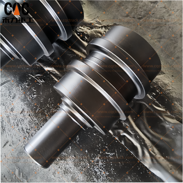
1.4 Component Anatomy and Design Features
The carrier roller assembly for HYUNDAI R700/R800/R850 series comprises several key components engineered for extreme-duty operation:
Roller Body: The main wheel that contacts and supports the track chain, manufactured from forged alloy steel with induction-hardened tread and flange surfaces. The body incorporates precision-machined bearing bores and seal housing cavities.
Shaft: The stationary axle that mounts to the track frame via robust brackets, manufactured from high-strength alloy steel with precision-ground bearing journals and surface treatments for enhanced durability.
Bearing System: Matched sets of heavy-duty tapered roller bearings that provide smooth rotation while accommodating combined radial and thrust loads. Bearings are selected with dynamic load ratings appropriate for 70-85 ton class machines.
Sealing System: Multi-stage contamination barriers that protect the bearings from abrasive particles, moisture, and debris. Includes floating seals, lip seals, and labyrinth dust guards.
Mounting Bracket: Heavy-duty fabricated or cast bracket that attaches the roller assembly to the track frame, designed to withstand the full dynamic loads of operation.
2. Metallurgical Foundation: Material Science for Ultra-Large Excavator Applications
2.1 Alloy Steel Selection Criteria for Extreme Duty
The service environment of a 70-85 ton class excavator carrier roller presents the most demanding material requirements in the heavy equipment industry. The component must simultaneously:
- Resist abrasive wear from continuous contact with the track chain and exposure to mining debris containing highly abrasive minerals such as quartz (hardness 7 Mohs), silicates, and granite
- Withstand impact loads from machine travel over rough mine terrain, crossing obstacles, and dynamic loading during excavation cycles
- Maintain structural integrity under cyclic loading exceeding 10⁷ cycles over the machine’s lifetime
- Preserve dimensional stability despite exposure to temperature extremes (-40°C to +50°C), moisture, and chemical contaminants including fuels, lubricants, and mining reagents
Premium manufacturers like CQC TRACK select specific premium alloy steel grades that achieve the optimal balance of hardness, toughness, and fatigue resistance for ultra-large excavator applications:
SAE 4140 / 42CrMo Chromium-Molybdenum Alloy: This is the preferred material for extreme-duty carrier rollers. With carbon content of 0.38-0.45%, chromium of 0.90-1.20%, and molybdenum of 0.15-0.25%, SAE 4140 provides:
- Ultimate tensile strength of 950 MPa or higher after proper heat treatment
- Excellent hardenability for through-hardening of large-section components (up to 100 mm section)
- Superior fatigue resistance for cyclic loading applications
- Good toughness at high hardness levels (Charpy V-notch impact values of 40-60 J at -20°C)
- Resistance to temper embrittlement during heat treatment
- Enhanced performance in low-temperature environments
SAE 4340 / 40CrNiMo Premium Alloy: For the most demanding mining applications, SAE 4340 with nickel addition (1.65-2.00%) provides:
- Even higher hardenability for very large sections
- Superior toughness at high strength levels
- Enhanced fatigue strength
- Better low-temperature impact properties
50Mn / 50MnB Manganese Steel: For roller bodies where enhanced wear resistance is prioritized, 50Mn with carbon 0.45-0.55% and manganese 1.4-1.8% provides:
- Excellent surface hardenability
- Good wear resistance from carbide formation
- Adequate toughness for most applications
- Boron micro-alloyed variants (50MnB) for enhanced hardenability
Material Traceability: Reputable manufacturers provide comprehensive material documentation, including Mill Test Reports (MTRs) certifying chemical composition with element-specific analysis (C, Si, Mn, P, S, Cr, Mo, Ni as applicable). Spectrographic analysis confirms alloy chemistry against certified specifications.
2.2 Forging vs. Casting: The Grain Structure Imperative
The primary forming method fundamentally determines the carrier roller’s mechanical properties and service life. While casting offers cost advantages for simple geometries, it produces an equiaxed grain structure with random orientation, potential porosity, and inferior impact resistance. Premium ultra-large excavator carrier roller manufacturers exclusively employ closed-die hot forging for the roller body.
The forging process for R700/R800/R850 class components begins with cutting large-diameter steel billets (typically 200-300 mm diameter) to precise weight, heating them to approximately 1150-1250°C until fully austenitized, then subjecting them to high-pressure deformation between precision-machined dies in hydraulic presses capable of 5,000-10,000 tons of force.
This thermo-mechanical treatment produces continuous grain flow that follows the component contour, aligning grain boundaries perpendicular to principal stress directions. The resulting structure exhibits 20-30% higher fatigue strength and significantly greater impact energy absorption compared to cast alternatives—a critical advantage in mining applications where impact loads can be severe.
After forging, components undergo controlled cooling to prevent the formation of detrimental microstructures such as Widmanstätten ferrite or excessive grain boundary carbide precipitation.
2.3 Dual-Property Heat Treatment Engineering
The metallurgical sophistication of a premium ultra-large excavator carrier roller manifests in its precisely engineered hardness profile—an extremely hard, wear-resistant surface coupled with a tough, impact-absorbing core:
Quenching and Tempering (Q&T) : The entire forged roller body is austenitized at 840-880°C, then rapidly quenched in agitated water, oil, or polymer solution. This transformation produces martensite—providing maximum hardness but with associated brittleness. Immediate tempering at 500-650°C allows carbon to precipitate as fine carbides, relieving internal stresses and restoring toughness. The resulting core hardness typically ranges from 280-350 HB (29-38 HRC), providing optimal toughness for impact absorption in ultra-large excavator applications.
Induction Surface Hardening: Following finish machining, the critical wear surface—the tread diameter—undergoes localized induction hardening. A precision-designed multi-turn copper inductor coil surrounds the component, inducing eddy currents that rapidly heat the surface layer to austenitizing temperature (900-950°C) within seconds. Immediate water quenching produces a martensitic case of 8-15 mm depth with surface hardness of HRC 55-62, providing exceptional resistance to abrasive wear from track chain contact in mining environments.
Hardness Profile Verification: Quality manufacturers perform microhardness traverses on sample components to verify case depth compliance with specifications. The hardness gradient from surface (HRC 55-62) through the hardened case to the core (280-350 HB) must follow a controlled transition to prevent spalling or case-core separation under impact loading. A typical hardness profile shows:
- Surface: HRC 58-62
- 2 mm depth: HRC 55-58
- 5 mm depth: HRC 50-55
- 8 mm depth: HRC 45-50
- 12 mm depth: HRC 35-45
- Core: HRC 29-38
2.4 Quality Assurance Protocols for Ultra-Large Excavator Components
Manufacturers like CQC TRACK implement multi-stage quality verification throughout production, with enhanced protocols for ultra-large excavator components:
- Spectroscopic Material Analysis: Confirms alloy chemistry against certified specifications at raw material receipt, with enhanced element verification for critical alloys. Chemistry must meet strict limits for all elements, particularly carbon, manganese, chromium, molybdenum, and nickel.
- Ultrasonic Testing (UT) : 100% inspection of critical forgings verifies internal soundness, detecting any centerline porosity, inclusions, or laminations that could compromise structural integrity under extreme loads. Testing follows ASTM A388 or equivalent standards.
- Hardness Verification: Rockwell or Brinell hardness testing confirms both core hardness after Q&T treatment and surface hardness after induction hardening. Enhanced sampling rates for ultra-large components (up to 100% for critical features).
- Magnetic Particle Inspection (MPI) : Examines critical areas—particularly flange roots and shaft transitions—detecting any surface-breaking cracks or grinding burns with enhanced sensitivity. Testing follows ASTM E709 or equivalent standards.
- Dimensional Verification: Coordinate Measuring Machines (CMM) verify critical dimensions, with statistical process control maintaining process capability indices (Cpk) exceeding 1.33 for critical features. Full dimensional reports are provided.
- Mechanical Testing: Sample components undergo tensile testing and impact testing (Charpy V-notch) at reduced temperatures (-20°C to -40°C) to verify toughness for cold-climate mining operations.
- Microstructural Evaluation: Metallographic examination verifies proper grain structure, case depth, martensitic structure, and absence of detrimental phases such as retained austenite or grain boundary carbides.
3. Precision Engineering: Component Design and Manufacturing
3.1 Roller Geometry for Ultra-Large Excavator Applications
The carrier roller geometry for R700/R800/R850 class machines must precisely match the track chain specifications while accommodating the extreme loads of mining operation:
Outer Diameter: The 350-420 mm diameter is calculated to provide appropriate rotational speed and bearing L10 life at typical travel speeds (1.5-3 km/h in mining applications). The diameter must be maintained within tight tolerances (±0.10 mm) to ensure consistent chain support height and proper engagement.
Tread Profile: The contact surface typically incorporates a slight crown (0.5-1.5 mm radius) to accommodate minor track misalignment and prevent edge loading that could accelerate localized wear. The profile is optimized through finite element analysis to ensure uniform pressure distribution across the contact patch under varying load conditions. Crown radius is carefully selected based on expected track misalignment and load conditions.
Flange Configuration: Carrier rollers for ultra-large excavators feature robust double-flange designs that provide positive track retention in both directions—essential for mining operations on side slopes. Critical flange design elements include:
| Feature | Specification | Engineering Significance |
|---|---|---|
| Flange Height | 22-28 mm | Provides robust lateral constraint to prevent derailment |
| Flange Width (radial thickness) | 20-30 mm | Ensures adequate strength for anti-derailment function |
| Flange Face Relief Angle | 8-12° | Facilitates debris ejection, prevents material packing |
| Flange Root Radius | 8-12 mm | Minimizes stress concentration, prevents crack initiation |
| Flange Face Hardness | HRC 55-62 | Wear resistance against track link sidebars |
Roller Width: The 130-160 mm overall width provides adequate contact surface with the track chain rail, distributing load to minimize contact pressure and wear. The tread width is typically 80-100 mm, with flanges extending beyond.
3.2 Shaft and Bearing System Engineering for Extreme Loads
The stationary shaft must withstand continuous bending moments and shear stresses while maintaining precise alignment with the rotating roller body. For R700/R800/R850 applications, shaft diameters typically range 90-110 mm, calculated based on:
- Static machine weight distributed to each carrier roller (800-1,500 kg per roller, depending on configuration)
- Dynamic load factors of 3.0-4.0 for mining applications (higher than construction due to impact)
- Track tension loads transmitted through the chain during operation
- Side loads during turning and slope operation (up to 30-40% of vertical load)
The bearing system for ultra-large excavator carrier rollers employs matched sets of heavy-duty tapered roller bearings, specifically selected for extreme-duty applications:
| Bearing Parameter | Specification | Engineering Significance |
|---|---|---|
| Bearing Type | Matched tapered roller bearings | Simultaneously supports high radial and thrust loads |
| Dynamic Load Rating (C) | 300-500 kN | Appropriate for 70-85 ton class machines |
| Static Load Rating (C0) | 500-800 kN | Withstands peak impact loads without permanent deformation |
| Cage Design | Machined brass cage | Superior strength for shock loading compared to stamped steel |
| Internal Clearance | C3 or C4 class | Accommodates thermal expansion during operation |
| Raceway Finish | Super-finished (Ra ≤0.1 µm) | Reduces friction, extends fatigue life |
| Roller Profile | Optimized crowning | Prevents edge loading under misalignment |
| Material | Case-hardened bearing steel | Maximum surface durability with tough core |
Premium manufacturers source bearings from reputable suppliers such as Timken®, NTN, KOYO, or equivalent high-quality bearing manufacturers with proven performance in mining applications.
The shaft bearing journals are precision-ground to h6 tolerance (±0.015-0.025 mm) and often surface-treated (e.g., chrome plating, nitriding, or induction hardening) for enhanced wear resistance and corrosion protection.
3.3 Advanced Multi-Stage Sealing Technology for Mining Environments
The seal system is the single most critical determinant of carrier roller longevity in ultra-large excavator mining applications, where machines operate in environments with extreme contamination levels. Industry data indicates that over 80% of premature roller failures in mining originate from seal compromise.
Premium ultra-large excavator carrier rollers from CQC TRACK employ multi-stage, mining-grade sealing systems specifically engineered for extreme contamination environments:
Primary Heavy-Duty Floating Seal: Precision-ground hardened iron or steel rings with lapped sealing faces achieving flatness within 0.5-1.0 µm. For mining applications, seal face materials and coatings are selected for:
| Seal Feature | Specification | Benefit |
|---|---|---|
| Seal Ring Material | Through-hardened steel or special iron alloy | Maximum wear resistance |
| Seal Face Flatness | ≤1.0 µm | Maintains continuous contact, prevents leakage |
| Seal Face Roughness | Ra ≤0.1 µm | Minimizes friction, extends life |
| Seal Face Coating | Titanium nitride or chromium nitride (optional) | Enhanced wear resistance for extreme abrasion |
| Seal Ring Hardness | HRC 58-64 | Resists abrasive wear from contaminants |
Secondary Radial Lip Seal: Manufactured from premium elastomer materials with:
- HNBR (Hydrogenated Nitrile Butadiene Rubber) : Exceptional temperature resistance (-40°C to +150°C), chemical compatibility with EP greases, enhanced abrasion resistance
- FKM (Fluoroelastomer) : For high-temperature applications or chemical exposure (optional)
- Positive sealing pressure maintained by garter spring
- Dust lip integrated design to exclude coarse contaminants
External Labyrinth-Style Dust Guard: Creates a tortuous path with multiple chambers that progressively trap coarse contaminants before they reach the primary seals. The labyrinth is:
- Packed with high-adhesion, extreme-pressure mining-grade grease
- Designed with expulsion channels for self-cleaning action during rotation
- Configured with multiple stages (typically 3-5 chambers) for maximum protection
- Protected by sacrificial wear rings that maintain seal alignment even as components wear
Grease Cavity: An intermediate cavity packed with mining-grade EP grease that acts as a barrier, expelling any potential contaminants that bypass the outer seals.
Pre-Lubrication: The bearing cavity is pre-filled with mining-grade, high-adhesion, extreme pressure (EP) grease containing:
- Molybdenum disulfide (MoS₂) or graphite for boundary lubrication under extreme pressure
- Enhanced anti-wear additives (ZDDP, phosphorus compounds) for shock load protection
- Corrosion inhibitors for wet mining environment operation
- Oxidation stabilizers for extended service intervals (2,000+ hours)
- Solid lubricants for emergency operation after lubrication breakdown
3.4 Mounting Bracket and Track Frame Interface
The carrier roller mounts to the track frame via robust mounting brackets that must withstand the full dynamic loads of mining operation. For R700/R800/R850 class machines, these brackets are substantial components weighing 20-40 kg each.
Critical design features include:
- Precision-Machined Mounting Surfaces: Ensure proper alignment and load distribution to the track frame. Surface flatness typically maintained within 0.1 mm over 100 mm.
- High-Strength Fasteners: Grade 12.9 bolts (typically M24-M30) with controlled tightening specifications (torque values 800-1,500 Nm depending on size).
- Positive Locking Features: Tab washers, locking plates, or thread-locking compounds to prevent loosening under severe vibration.
- Wear Plates: Hardened steel wear plates at the bracket-to-frame interface, providing sacrificial surfaces that protect the main components.
- Grease Fittings: Equipped for scheduled re-lubrication of sliding interfaces (if applicable).
- Corrosion Protection: Heavy-duty paint systems (epoxy or polyurethane) or zinc-rich coatings for mine environment durability, often with dry film thickness of 150-250 µm.
3.5 Precision Machining and Quality Control
Modern CNC machining centers achieve dimensional tolerances that directly correlate with service life in ultra-large excavator applications. Critical parameters for R700/R800/R850 class carrier rollers include:
| Feature | Typical Tolerance | Measurement Method | Consequence of Deviation |
|---|---|---|---|
| Shaft Journal Diameter | h6 to h7 (±0.015-0.025 mm) | Micrometer (0.001 mm resolution) | Clearance affects lubrication film and load distribution |
| Bearing Bore Diameter | H7 to H8 (±0.020-0.035 mm) | Bore gauge / CMM | Fit with bearing outer race; incorrect fit causes premature bearing failure |
| Seal Housing Bore | H8 to H9 (±0.025-0.045 mm) | Bore gauge / CMM | Seal compression affects sealing force and life |
| Tread Diameter | ±0.10 mm | Micrometer / CMM | Consistent chain support height |
| Flange-to-Flange Distance | ±0.15 mm | CMM | Proper track link engagement and guidance |
| Flange Parallelism | ≤0.05 mm across diameter | CMM | Misalignment induces uneven wear and side loading |
| Tread Runout | ≤0.15 mm total indicated | Dial indicator / CMM | Vibration and track chain impact |
| Concentricity | ≤0.10 mm | CMM | Smooth rotation and even wear distribution |
| Surface Finish (tread) | Ra ≤1.6 µm | Profilometer | Wear rate and chain interaction |
| Surface Finish (bearing journals) | Ra ≤0.4 µm | Profilometer | Bearing life and lubrication |
| Surface Finish (seal areas) | Ra ≤0.4 µm | Profilometer | Seal wear rate and leakage prevention |
CNC-controlled turning and grinding processes guarantee precise geometry and surface finish for smooth track chain interaction. In-process dimensional verification with real-time feedback to machine operators enables immediate correction of process drift.
3.6 Assembly and Pre-Delivery Testing
Final assembly is performed in clean-room conditions to prevent contamination—a critical requirement for components where even microscopic contaminants can initiate premature wear. Assembly protocols include:
- Component Cleaning: Ultrasonic cleaning of all components before assembly using specialized cleaning solutions that remove all machining residues, oils, and particulates.
- Controlled Environment: Positive-pressure clean areas with HEPA filtration (Class 100,000 or better) and temperature/humidity control.
- Bearing Installation: Precision pressing with force monitoring to ensure proper seating; bearings are heated for expansion to facilitate installation without damage (induction heaters with temperature control).
- Preload Setting: Tapered roller bearings are adjusted to specified preload using specialized fixtures and torque measurement (typically 10-30 N-m rotational torque).
- Seal Installation: Specialized hydraulic or mechanical presses with alignment fixtures prevent damage to sealing lips and faces; seal faces are lubricated during installation.
- Lubrication: Measured grease fill with specified mining-grade lubricants; air pockets are eliminated during filling through controlled pressure and venting.
- Rotation Testing: Verification of smooth rotation and correct bearing preload.
Pre-delivery testing for ultra-large excavator carrier rollers includes:
- Rotational torque test to verify smooth rotation and correct bearing preload (measurement of breakaway and running torque)
- Seal integrity test with pressurized air (0.5-1.0 bar) and soap solution to detect leakage paths; more sophisticated testing may use pressure decay monitoring (loss <0.1 bar/minute)
- Dimensional inspection of the assembled unit to verify all critical fits (CMM verification)
- Visual inspection of seal installation, fastener torque, and overall workmanship
- Mechanical run-in on sample basis to verify performance under simulated loads
- Ultrasonic re-inspection of critical areas after final machining (shaft journals, flange roots)
4. CQC TRACK: Manufacturer Profile and Capabilities for Ultra-Large Excavator Components
4.1 Company Overview and Industry Position
CQC TRACK (operating under HELI Group affiliation) is a specialized industrial manufacturer and supplier of heavy-duty undercarriage systems and chassis components, operating on both ODM and OEM principles. Based in Quanzhou, Fujian Province—a region recognized for specialized expertise in customized undercarriage solutions—the company has established itself as a significant player in the global undercarriage components market, with particular strength in ultra-large excavator and mining equipment components.
With specialized focus on undercarriage components for global markets, CQC TRACK has developed comprehensive capabilities across the entire undercarriage product spectrum, including track rollers, carrier rollers, front idlers, sprockets, track chains, and track shoes for applications ranging from mini excavators to ultra-large mining-class machines up to 200 tons. The company serves as a source factory and manufacturer for heavy-duty tracked excavator chassis components, supplying international distributors, mining operations, equipment dealers, and aftermarket networks worldwide.
4.2 Technical Capabilities and Engineering Expertise for Ultra-Large Excavator Applications
Integrated Heavy-Duty Manufacturing: CQC TRACK controls the full production cycle from material sourcing and forging to precision machining, heat treatment, assembly, and quality testing. For HYUNDAI R700/R800/R850 class components, this vertical integration ensures consistent quality and complete traceability throughout the manufacturing process—essential for components that must perform reliably under extreme mining conditions.
Advanced Metallurgical Expertise: The company’s technical team leverages advanced metallurgical knowledge and dynamic load simulation tools to design components for ultra-large excavator duty cycles. For R700/R800/R850 class carrier rollers, this includes:
- Material Selection: Premium SAE 4140/42CrMo alloy steel with UTS ≥950 MPa, sourced from certified steel mills with full traceability
- Heat Treatment: Quenched and tempered to core hardness 280-350 HB, followed by induction hardening to surface HRC 58-62 with case depth 8-15 mm
- Finite Element Analysis (FEA) : Stress distribution analysis under mining loads to optimize geometry and minimize stress concentration
- Fatigue Life Prediction: Based on mining duty cycle data (load spectra, impact frequency, travel distances)
- Sealing Technology: Multi-stage labyrinth seal or float seal configuration with premium elastomers for extreme contamination protection
Design Innovations: CQC TRACK’s engineering team incorporates design elements specifically for ultra-large excavator mining applications:
- Enhanced seal systems for extreme contamination environments (quartz, silicate dust)
- Optimized flange geometries for mining terrain operation (side slopes up to 30°)
- Reinforced bearing configurations with higher dynamic load ratings
- Corrosion-resistant coatings for wet mining conditions
- Wear indicator features for maintenance planning
- Grease-purge channels with Zerk fittings (NLGI #2 EP grease)
Quality Assurance Protocols: Production is governed by a Quality Management System (QMS) aligned with international standards (ISO 9001). Each batch undergoes rigorous inspection, including:
- 100% ultrasonic testing of critical forgings
- Enhanced sampling rates for hardness verification (10-20% of production)
- Extended dimensional verification protocols (CMM inspection of all critical features)
- Mining-specific test criteria and acceptance standards
- Comprehensive documentation packages for quality traceability
- ISO 6015:2019 verified performance
Engineering Support: The company’s engineering team provides technical support for application verification, ensuring correct part selection for specific HYUNDAI models and production years. Their expertise lies in reverse-engineering and manufacturing aftermarket parts that meet or exceed original equipment performance.
4.3 Product Range for HYUNDAI Ultra-Large Excavators
CQC TRACK manufactures a comprehensive range of undercarriage components for HYUNDAI’s largest excavator models, including:
| Component Type | Compatible Models | HYUNDAI Part Numbers |
|---|---|---|
| Carrier Roller (Upper Roller) | R700, R800, R850 | 81ND12050 |
| Track Roller (Bottom Roller) | R700, R800, R850 | Various |
| Front Idler Assembly | R700, R800, R850 | Various |
| Sprocket / Drive Segment | R700, R800, R850 | Various |
| Track Chain Assembly | R700, R800, R850 | Various pitches |
| Track Shoes | R700, R800, R850 | Various widths |
The company maintains tooling and production capability for multiple HYUNDAI ultra-large excavator models, ensuring consistent supply for both current production and field support requirements. Their extensive model coverage spans excavators from 5 tons to 200 tons and dozers from D20 through D475.
4.4 Global Supply Capability for Mining Operations
CQC TRACK has strengthened its technical services in geographic areas closest to its mining customers, with particular attention to:
- Major mining regions: Australia (Pilbara, Bowen Basin), Indonesia (Kalimantan, Sumatra), South Africa (Witwatersrand, Northern Cape), Chile (Atacama), Peru (Andes), Canada (Alberta, British Columbia), Russia (Siberia)
- Infrastructure development zones: Middle East (Saudi Arabia, UAE), Southeast Asia (Vietnam, Thailand, Indonesia), Africa (Nigeria, Kenya, Ghana)
- Heavy construction markets: North America, Europe, China
With production facilities in Quanzhou and strategic partnerships across China’s undercarriage manufacturing ecosystem, CQC TRACK offers:
- Competitive lead times: Typically 35-55 days for custom ultra-large excavator production
- Flexible minimum order quantities: Suitable for both mine-site inventory programs and just-in-time maintenance requirements
- Emergency response capability: Expedited production (15-25 days) for critical downtime situations
- Technical field support: Engineering consultation for application optimization
- Inventory programs: Stocking arrangements for high-demand components
- Consignment stock: Available for major mining operations
5. HYUNDAI R700/R800/R850 Series Overview
5.1 Machine Classification and Applications
The HYUNDAI R700, R800, and R850 series represent the pinnacle of HYUNDAI’s excavator lineup, designed and built for the most demanding mining and heavy construction applications worldwide:
| Model | Operating Weight | Engine Power | Typical Applications |
|---|---|---|---|
| R700 | 65-70 tons | 350-400 kW | Large-scale mining, major quarrying, heavy infrastructure |
| R800 | 75-80 tons | 400-450 kW | Open-pit mining, primary overburden removal |
| R850 | 80-85 tons | 450-500 kW | Ultra-large mining, major excavation projects |
These machines feature:
- Heavy-duty undercarriage systems designed for 20,000+ hour service life in mining conditions
- Mining-grade components throughout, including carrier rollers engineered for extreme duty
- Advanced hydraulic systems for maximum productivity and efficiency (dual-pump, independent boom and swing)
- Operator-focused cabs with comprehensive monitoring and control systems
- Global service support through HYUNDAI’s worldwide dealer network
5.2 Undercarriage System Specifications
The undercarriage system for R700/R800/R850 class machines represents the state of the art in heavy-duty track design:
| Component | Typical Specification | Mining Duty Features |
|---|---|---|
| Track Chain Pitch | 260-300 mm | Heavy-duty sealed and lubricated design (SALT or equivalent) |
| Track Shoe Width | 600-900 mm | Multiple widths for ground pressure optimization (mining, quarry, construction) |
| Number of Track Rollers | 8-10 per side | Heavy-duty sealed rollers with dual-flange configuration |
| Number of Carrier Rollers | 2-3 per side | Mining-class upper rollers with enhanced seals and double-flange design |
| Track Gauge | 3,000-3,600 mm | Wide stance for stability on side slopes |
| Ground Pressure | 80-120 kPa | Optimized for mine floor conditions (varies with shoe width) |
The carrier rollers in this system must support track chain spans of 2-4 meters between supports, with chain weights exceeding 300 kg per meter in the largest configurations—resulting in static loads of 800-1,500 kg per roller before dynamic factors are applied.
5.3 Mining Duty Cycle Considerations for R-Series Excavators
Carrier rollers in mining applications experience duty cycles significantly more severe than construction applications:
- Continuous operation: Often 20+ hours per day, 6-7 days per week, with minimal downtime
- High travel distances: Frequent repositioning across mine sites (up to 5-10 km per shift)
- Rough terrain: Operation on unimproved mine roads, blasted rock, and uneven benches
- Extreme temperatures: From arctic cold (-40°C) to desert heat (+50°C)
- Contamination: Exposure to abrasive dust (quartz, silicates), mud, water, and chemicals (fuels, lubricants, process reagents)
- Impact loading: Travel over mine debris, crossing conveyor belts, and traversing rough terrain
- Side slope operation: Mining on benches with slopes up to 30°
These conditions demand carrier rollers with enhanced specifications, robust sealing, and quality assurance beyond standard heavy-duty components. The 81ND12050 carrier roller is specifically engineered to meet these demanding requirements.
6. Performance Validation and Service Life Expectations for Mining Applications
6.1 Benchmarks for 70-85 Ton Class Excavator Carrier Rollers
Field data from diverse mining and heavy construction operations provides realistic performance expectations for HYUNDAI R700/R800/R850 class carrier rollers:
| Application Severity | Operating Environment | Expected Service Life |
|---|---|---|
| Heavy Construction | Major earthmoving, varied terrain | 6,000-8,000 hours |
| Quarry Operations | Continuous operation, moderate abrasion | 5,000-7,000 hours |
| Mining – Moderate | Mixed ore/waste, maintained haul roads | 4,500-6,000 hours |
| Mining – Severe | Highly abrasive ore (quartz, granite), rough terrain | 3,500-5,000 hours |
| Mining – Extreme | Ultra-abrasive conditions, continuous impact | 2,500-4,000 hours |
Premium aftermarket carrier rollers from reputable manufacturers like CQC TRACK demonstrate performance parity with OEM mining-class components, achieving 85-95% of OEM service life at significantly lower acquisition cost (typically 30-50% below OEM pricing). ISO 6015:2019 verified service life of 10,000+ hours is achievable in optimal conditions with proper maintenance.
6.2 Common Failure Modes in Ultra-Large Excavator Mining Applications
Understanding failure mechanisms enables proactive maintenance and informed procurement decisions for mining operations:
Seal Failure and Contamination Ingress: The predominant failure mode in mining applications (70-80% of failures), seal compromise allows abrasive particles to enter the bearing cavity. Mining environments with high concentrations of quartz (hardness 7 Mohs) and silicates accelerate seal wear and contaminant ingress exponentially. Initial symptoms include:
- Grease leakage around seals (visible as wetness or accumulated debris)
- Increasing operating temperature (detectable by infrared thermography; 10-20°C above baseline)
- Rough rotation as contamination initiates bearing wear
- Progressive increase in running torque
- Grinding or rumbling noises during operation
- Eventually, seizure or catastrophic bearing failure
Flange Wear: Progressive wear on flange faces indicates inadequate surface hardness or improper track alignment. In mining applications, this can be accelerated by:
- Frequent operation on side slopes (mining benches)
- Tight turning on abrasive surfaces
- Track misalignment from worn components or frame damage
- Impact damage from debris trapped between flange and track link
Critical wear indicators include thinning of flange width (reducing lateral constraint) and development of sharp edges (increasing stress concentration and risk of derailment).
Tread Wear and Diameter Reduction: The roller tread gradually wears from continuous contact with track bushings. When tread diameter reduction exceeds specifications (typically 12-18 mm for this size class), several consequences occur:
- Reduced chain support height, affecting engagement geometry
- Increased contact pressure due to reduced contact area
- Accelerated wear of both roller and chain
- Potential for reduced wrap angle affecting chain guidance
- Increased dynamic loading from chain slapping
Bearing Fatigue: After extended service, bearings may exhibit spalling due to subsurface fatigue, indicating the component has reached its natural life limit. In mining applications, this is often accelerated by:
- Higher-than-expected dynamic loading from severe terrain
- Contamination-induced surface distress from seal breaches
- Lubricant degradation from high operating temperatures
- Misalignment from frame deflection or worn components
- Impact loading from shock events
Shaft Fatigue: In severe applications with repetitive high-impact loading, shaft fatigue cracks may develop at stress concentration points (typically at changes in section or at the inboard side of bearing journals). These cracks can propagate undetected and lead to catastrophic shaft failure if not identified during inspection.
Bracket Failure: The mounting bracket may experience fatigue cracking or deformation under extreme loading, particularly if impacted by debris or if bolts become loose.
6.3 Wear Indicators and Inspection Protocols for Mining Operations
Regular inspection at 250-hour intervals (or weekly for continuous mining operations) should check for:
- Seal condition: Grease leakage, debris accumulation around seals, seal damage, evidence of recent purging
- Roller rotation: Smoothness, noise, binding, rotational resistance (check by hand with track raised)
- Operating temperature: Comparison with baseline and sister rollers using infrared thermometer or thermal imaging camera
- Flange condition: Wear measurement (thickness), sharp edges, damage, cracks (visual and with calipers)
- Tread condition: Wear pattern analysis, diameter measurement (using pi tape or large calipers), surface damage, spalling
- Mounting integrity: Fastener torque marking, bracket condition, alignment, evidence of movement
- Frame interface: Wear plate condition, clearance, lubrication
- Radial play: Vertical movement detection (pry bar and dial indicator)
- Axial play: Lateral movement detection
- Unusual noises: Grinding, squeaking, knocking, rumbling during operation
- Visual evidence: Flat spots on roller (indicates sticking)
Advanced inspection techniques for mining operations may include:
- Ultrasonic thickness measurement of tread and flange sections to quantify remaining wear allowance (using handheld ultrasonic gauges)
- Magnetic particle inspection (MPI) of shafts during major overhauls to detect fatigue cracks
- Thermographic imaging to identify bearing distress before failure (hot spots indicate increased friction)
- Vibration analysis for predictive maintenance programs (baseline and trend monitoring using accelerometers)
- Oil analysis of any serviceable bearings (rare in modern sealed designs)
- Borescope inspection of seal areas and bearing cavities through existing ports (if available)
7. Installation, Maintenance, and Service Life Optimization for Mining Applications
7.1 Professional Installation Practices for HYUNDAI Ultra-Large Excavators
Proper installation significantly impacts carrier roller service life in R700/R800/R850 class machines:
Track Frame Preparation: The mounting surfaces on the track frame must be clean, flat, and free of burrs, corrosion, or damage. Critical steps include:
- Thorough cleaning of mounting pads and bolt holes (wire brush, solvent)
- Inspection for cracks or damage around mounting areas
- Measurement of mounting surface flatness (should be within 0.2 mm over 100 mm)
- Repair of any damaged threads (helicoils or thread inserts as needed)
- Replacement of worn wear plates or liners
Bracket Inspection and Preparation: The mounting brackets themselves should be inspected for:
- Wear or deformation of mounting surfaces
- Crack initiation at stress points (visual and MPI if indicated)
- Corrosion damage
- Thread condition in mounting holes
- Proper fit to track frame
Fastener Specifications: All mounting bolts must be:
- Grade 12.9 as specified (typically M24-M30)
- Clean and lightly oiled before installation
- Tightened in proper sequence to specified torque using calibrated torque wrenches (typically 800-1,500 Nm)
- Equipped with appropriate locking features (lock washers, thread locker, locking plates)
- Marked after torquing for visual inspection
- Retorqued after initial operation (typically 50-100 hours)
Alignment Verification: After installation, verify that:
- The roller is properly aligned with the track chain path (check with straightedge)
- The roller contacts the track chain evenly across its width (feeler gauges)
- Flange clearances to track links are within specification (typically 4-8 mm total)
- The roller rotates freely without binding or interference
Track Tension Adjustment: After installation, verify proper track tension according to machine specifications. For 70-85 ton class excavators in mining applications, proper sag typically ranges 40-60 mm measured at the center of the lower track run between the front idler and first track roller. Check tension after a few hours of operation and readjust if necessary.
7.2 Preventive Maintenance Protocols for Mining Operations
Regular Inspection Intervals: Visual inspection at 250-hour intervals (weekly for continuous mining operations) should check for all wear indicators previously described. More frequent inspection (daily walk-around) should include visual check for obvious seal leakage, damage, or unusual conditions.
Track Tension Management: Proper track tension directly impacts carrier roller life. Excessive tension increases bearing loads; insufficient tension allows chain slapping that accelerates seal deterioration and increases impact loads. Check tension:
- At every 250-hour service interval
- After the first 10 hours on new components
- When operating conditions change significantly (e.g., moving from soft to rocky terrain)
- When abnormal track behavior is observed (slapping, squeaking, uneven wear)
Cleaning Protocols: In mining environments, proper cleaning is essential but must be performed correctly:
- Avoid high-pressure washing directed at seal areas, which can force contaminants past seals
- Use low-pressure water (below 1,500 psi) for general cleaning
- Remove accumulated debris from around rollers during daily inspections using scrapers or compressed air
- Allow components to dry thoroughly before extended idle periods in cold climates
- Consider compressed air for blowing out packed material, but avoid directing at seals
Lubrication: For carrier rollers with sealed bearings, no additional lubrication is required during service life. For any serviceable components:
- Use specified mining-grade greases with appropriate additives (EP, MoS₂, corrosion inhibitors)
- Follow recommended intervals and quantities (typically 500-1,000 hours for serviceable designs)
- Purge until clean grease appears at relief points (for serviceable bearings)
- Wipe fittings clean before and after lubrication
- Record lubrication history for trend analysis
Operating Practice Considerations: Operator practices significantly impact carrier roller life:
- Minimize high-speed travel over rough terrain (reduce speed to 2-3 km/h on rough ground)
- Avoid sudden direction changes that impose high side loads
- Reduce travel speed when crossing obstacles
- Keep track tension properly adjusted for conditions
- Report unusual noises or handling immediately
- Avoid operation with severely worn track components that can accelerate new roller wear
- Maintain consistent travel paths to distribute wear evenly when possible
- Avoid operating with track chains that have excessive slack
Environmental Considerations:
- In wet conditions (mines with high water table, rainy seasons), inspect seals more frequently for water ingress
- In freezing conditions (Arctic/Subarctic mines), ensure rollers are free of ice before operation
- In high-temperature environments (desert mines, tropical operations), monitor operating temperatures closely
- In highly abrasive conditions (quartzite, iron ore mines), consider more frequent inspection intervals (every 100-150 hours)
7.3 Replacement Decision Criteria for Mining Applications
Carrier rollers for R700/R800/R850 class machines should be replaced when:
- Seal leakage is evident and cannot be stopped (visible grease loss, accumulated debris indicating active leakage)
- Radial play exceeds manufacturer specifications (typically 4-6 mm measured at tread with track raised)
- Axial play exceeds manufacturer specifications (typically 3-5 mm)
- Flange wear reduces guidance effectiveness (flange thickness reduced by more than 25-30%)
- Flange damage includes cracks, spalling, or severe deformation
- Tread wear exceeds hardened case depth (typically when diameter reduction exceeds 12-18 mm)
- Tread diameter reduction impairs proper chain support (visible change in chain sag pattern)
- Surface spalling affects more than 10-15% of contact area
- Bearing rotation becomes rough, noisy, or irregular (increased running torque)
- Operating temperature consistently exceeds 80°C above ambient (indicating bearing distress)
- Visible damage includes cracks, impact damage, or deformation
- Roller is stuck (flat side visible) due to contamination
- Mounting integrity is compromised by worn or damaged brackets
7.4 System-Based Replacement Strategy for Mining Operations
For optimal undercarriage performance and cost efficiency in mining applications, the carrier roller condition should be evaluated alongside:
- Track chain: Pin and bushing wear (measured as % of original diameter, typically 5-8% replacement threshold), rail condition (height reduction, profile wear), seal effectiveness, overall elongation (typically 2-3% replacement threshold for mining)
- Track rollers (bottom) : Seal condition, tread wear, bearing condition across all rollers
- Front idler: Tread and flange condition, bearing condition, yoke wear
- Sprocket: Tooth wear profile (hook wear, tooth thinning), segment condition, mounting integrity
- Track frame: Alignment, wear plate condition, structural integrity
Replacing severely worn components in a matched set is considered best practice to prevent accelerated wear on new parts. Industry best practice recommends:
- Replace in pairs: Carrier rollers on both sides should be replaced together to maintain balanced track performance
- Replace in sets: When multiple rollers show significant wear, consider replacing all rollers on that side
- Consider system replacement: When track chain, rollers, idler, and sprocket all show significant wear (typically at 8,000-12,000 hours), full undercarriage replacement may be most cost-effective
- Schedule during major service: Plan replacement during scheduled downtime (preventive maintenance shutdowns) to minimize production impact
For mining operations with multiple machines, developing component life data enables predictive replacement planning, optimizing parts inventory and minimizing unplanned downtime. Key metrics to track include:
- Hours to first measurable wear
- Wear rate (mm per 1,000 hours) under specific conditions
- Failure modes and root causes analysis
- Performance comparisons between suppliers
- Impact of operating conditions (ore type, terrain, operator practices) on life
8. Strategic Sourcing Considerations for Mining Operations
8.1 The OEM vs. Aftermarket Decision for Ultra-Large Excavators
Mining equipment managers must evaluate the OEM versus high-quality aftermarket decision through multiple lenses:
Cost Analysis: Aftermarket components from manufacturers like CQC TRACK typically offer 30-50% initial cost savings compared to OEM parts. For mining fleets with multiple HYUNDAI R700/R800/R850 class machines operating 5,000+ hours annually, this differential can represent hundreds of thousands of dollars in annual savings. Total cost of ownership calculations must factor in:
| Cost Factor | OEM Consideration | Aftermarket Consideration |
|---|---|---|
| Initial Purchase Price | Baseline | 30-50% lower |
| Expected Service Life | Baseline | 85-95% of OEM |
| Maintenance Labor Cost | Similar | Similar |
| Downtime Cost | Similar | Similar |
| Warranty Coverage | 1-2 years / 2,000-3,000 hours | 1-2 years / 3,000-5,000 hours |
| Parts Availability | Variable (may be delayed) | Generally faster (4-8 weeks) |
| Inventory Carrying Cost | Higher due to higher unit cost | Lower due to lower unit cost |
Quality Parity: Premium aftermarket manufacturers achieve performance parity with OEM mining-class components through:
- Equivalent material specifications (SAE 4140/42CrMo with certified chemistry)
- Comparable heat treatment processes (core 280-350 HB, surface HRC 58-62, case depth 8-15 mm)
- Mining-grade sealing systems with multi-stage contamination protection
- Matched bearing sets from reputable bearing manufacturers (Timken®, NTN, KOYO)
- Rigorous quality control with 100% NDT of critical components
- ISO 9001 certified quality management systems
- ISO 6015:2019 verified performance
CQC TRACK’s quality protocols ensure consistent quality suitable for the most demanding mining applications.
Warranty Considerations: OEM warranties typically cover 1-2 years or 2,000-3,000 hours, with strict installation requirements and parts sourcing through authorized dealer networks. Reputable aftermarket manufacturers offer comparable warranties covering manufacturing defects, with coverage periods of 1-2 years and flexibility regarding installation providers. Key warranty considerations:
- Coverage scope (materials, workmanship, performance against specifications)
- Proration terms (full replacement vs. time-based proration)
- Claim processing time and requirements (documentation, return authorization)
- Field service support for claim verification
- Advance replacement options for critical components
Availability and Lead Times: OEM parts may face extended lead times due to centralized distribution and potential supply chain disruptions—critical considerations for mining operations where downtime costs can exceed $1,000-2,000 per hour. Aftermarket manufacturers with local production often deliver within 4-8 weeks, with emergency expediting available for critical situations (as fast as 2-3 weeks). CQC TRACK’s integrated manufacturing enables:
- Responsive order fulfillment for both standard and custom requirements
- Inventory programs for high-demand components
- Emergency production slots for critical needs
- Consignment stock options for large fleets
Technical Support: Aftermarket suppliers with mining engineering expertise can provide:
- Application engineering support for specific operating conditions (ore type, terrain, climate)
- Custom modifications for unique requirements (enhanced seals, modified materials)
- Field service support for installation and troubleshooting
- Component life data for predictive maintenance planning
- Training for maintenance personnel
- Failure analysis services (root cause determination)
8.2 Supplier Evaluation Criteria for Mining Applications
Procurement professionals for mining operations should apply rigorous evaluation frameworks when assessing potential carrier roller suppliers:
Manufacturing Capability Assessment: Facility evaluations should verify the presence of:
| Capability | Requirement | Verification Method |
|---|---|---|
| Forging Equipment | Large-capacity hydraulic presses (5,000+ tons) | Facility tour, equipment specifications |
| CNC Machining Centers | Large-envelope machines (2+ meter capacity) with precision capability | Equipment list, facility tour |
| Heat Treatment Facilities | Automated lines with atmosphere control, quenching systems for large components, tempering furnaces | Process documentation, facility tour |
| Induction Hardening | Multi-station induction equipment with process monitoring and verification | Equipment specifications, process records |
| Clean-Room Assembly | Positive-pressure areas with contamination control for seal installation | Facility tour, cleanliness verification |
| Testing Facilities | UT, MPI, CMM, metallurgical laboratory, hardness testers | Equipment list, calibration records |
| Quality Management | Documented procedures, calibration systems, traceability | ISO certificate, audit reports |
Quality Management Systems: ISO 9001:2015 certification represents the minimum acceptable standard for mining components. Suppliers with additional certifications demonstrate enhanced commitment to quality:
- ISO/TS 16949 for automotive-grade quality systems (excellent for high-volume precision)
- ISO 14001 for environmental management
- OHSAS 18001 / ISO 45001 for occupational health and safety
- CE marking for European market compliance
- Specific customer certifications (if applicable)
Material and Process Transparency: Reputable manufacturers readily provide:
- Material certifications (MTRs) with full chemistry and mechanical properties (tensile, yield, elongation, reduction of area)
- Heat treatment process documentation and verification records (time-temperature profiles, quench medium, tempering parameters)
- Inspection reports for dimensional verification and NDT (UT, MPI)
- Sample testing capability for customer verification
- Metallurgical analysis upon request (microstructure, case depth, hardness profile)
- Process flow diagrams and control plans
Production Capacity and Lead Times: Mining operations require reliable supply:
- Typical lead times for custom mining-class production: 35-55 days
- Inventory programs for critical components
- Emergency response capability for unplanned failures (15-25 days)
- Capacity to support multiple machines or entire fleets
- Scalability for growing requirements
Experience and Reputation: Suppliers with extensive experience in mining applications demonstrate sustained capability:
- Years in business serving mining customers (10+ years preferred)
- Reference accounts in similar mining operations (by commodity, region)
- Case studies of successful applications
- Industry recognition and certifications
- Technical publications and presentations
- Participation in industry associations (SAE, ISO committees)
Financial Stability: Long-term supply relationships require financially stable partners:
- Credit ratings and financial statements
- Banking relationships
- Investment in facilities and equipment
- Order backlog and capacity utilization
- Customer concentration (diversification)
8.3 The CQC TRACK Advantage for HYUNDAI Mining Applications
CQC TRACK offers several distinct advantages for HYUNDAI ultra-large excavator undercarriage procurement:
- Mining-Class Manufacturing Capability: Components engineered specifically for extreme-duty mining applications, with enhanced specifications beyond standard heavy-duty components
- Integrated Production Control: Full vertical integration from material sourcing through final assembly ensures consistent quality and complete traceability—essential for mining operations
- Material Excellence: Premium SAE 4140/42CrMo alloy steel with UTS ≥950 MPa, surface hardness HRC 58-62, case depth 8-15 mm for optimal wear resistance in mining environments
- Mining-Grade Sealing: Advanced multi-stage sealing systems with floating seals, HNBR lip seals, and labyrinth dust guards designed for extreme contamination (quartz, silicate dust)
- Comprehensive Quality Assurance: Enhanced testing protocols including 100% ultrasonic inspection of critical forgings, magnetic particle inspection of shafts, CMM dimensional verification
- Application Expertise: Technical team with deep understanding of HYUNDAI undercarriage systems and mining duty cycle requirements
- Global Supply Capability: Established distribution networks serving major mining regions worldwide with reliable lead times
- Competitive Economics: 30-50% cost savings while maintaining mining-class quality
- Engineering Support: Customization capabilities for specific operating conditions, including enhanced seal packages, modified material grades, and geometry adjustments
- Inventory Programs: Flexible stocking arrangements for mining operations to ensure immediate availability
9. Market Analysis and Future Trends for Mining Undercarriage Components
9.1 Global Demand Patterns
The global market for ultra-large excavator undercarriage components continues expanding, driven by:
Commodity Demand Growth: Increasing global demand for minerals, metals, and aggregates drives expansion of mining operations worldwide. Key commodities driving demand:
- Iron ore (Australia, Brazil, South Africa)
- Copper (Chile, Peru, Zambia, DRC)
- Coal (Australia, Indonesia, South Africa, USA)
- Gold (worldwide)
- Bauxite (Australia, Guinea, Brazil)
- Oil sands (Canada)
Infrastructure Development: Major infrastructure initiatives across Southeast Asia, Africa, the Middle East, and South America sustain demand for heavy equipment and replacement parts. Government spending on transportation, energy, and water projects drives equipment utilization and parts consumption.
Mining Fleet Expansion: New mine development and expansion of existing operations in resource-rich regions create demand for new equipment and establish ongoing parts requirements. The HYUNDAI R-series, particularly popular in Asian and African mining operations, generates significant aftermarket demand.
Equipment Fleet Aging: Many mining operations have extended equipment retention periods due to capital constraints, increasing aftermarket parts consumption as machines operate beyond 40,000-60,000 hours, requiring multiple undercarriage rebuilds.
9.2 Technological Advancements
Emerging technologies are transforming undercarriage component manufacturing for mining applications:
Advanced Materials Development: Research into nano-modified steels and advanced heat treatment cycles promises next-generation materials with enhanced wear resistance (20-30% improvement) without sacrificing toughness—particularly valuable for mining applications where wear life directly impacts operating cost.
Induction Hardening Optimization: Advanced induction systems with real-time temperature monitoring and feedback control achieve unprecedented uniformity in case depth (±1 mm) and hardness distribution (±2 HRC), extending wear life while reducing energy consumption.
Automated Assembly and Inspection: Robotic assembly systems with integrated vision inspection ensure consistent seal installation and dimensional verification, eliminating human variability in critical processes. Machine vision systems can detect defects invisible to the human eye (micron-level seal damage).
Predictive Maintenance Technologies: Embedded sensors in undercarriage components can monitor temperature, vibration, and wear in real time, enabling predictive maintenance and reducing unplanned downtime—particularly valuable for remote mining operations. Wireless sensor networks and IoT platforms enable fleet-wide monitoring.
Digital Twin Simulation: Advanced simulation tools enable manufacturers to model component performance under specific operating conditions, optimizing designs for particular applications and environments. FEA and multi-body dynamics simulations predict wear patterns and fatigue life.
Additive Manufacturing: For prototype and low-volume production, additive manufacturing enables rapid iteration of complex geometries and custom features, though not yet cost-effective for high-volume production of large mining components.
9.3 Sustainability and Remanufacturing
Growing emphasis on sustainability in mining operations is driving interest in remanufactured undercarriage components:
- Component Rebuilding: Processes for reclaiming and rebuilding worn carrier rollers, extending component life and reducing environmental impact. Rebuilding can restore 80-100% of original life at 50-70% of new cost.
- Material Recovery: Recycling of worn components for material recovery, with steel scrap value partially offsetting replacement cost.
- Life Extension Technologies: Advanced welding and hardfacing processes for component refurbishment, including submerged arc welding, laser cladding, and plasma transfer arc for tread and flange rebuilding.
- Circular Economy Initiatives: Programs for core return and remanufacturing, reducing waste and raw material consumption.
- Carbon Footprint Reduction: Remanufacturing typically requires 80-90% less energy than new production, significantly reducing carbon footprint.
CQC TRACK is developing capabilities in component remanufacturing to support mining customers’ sustainability goals while providing cost-effective replacement options. The company’s integrated manufacturing expertise positions it well for quality remanufacturing programs.
10. Conclusion and Strategic Recommendations for Mining Operations
The HYUNDAI 81ND12050 track carrier roller assembly for R700, R800, and R850 excavators represents a precision-engineered mining-class component whose performance directly impacts machine availability, operating cost, and mine productivity. Understanding the technical intricacies—from alloy selection (SAE 4140/42CrMo) and forging methodology through precision machining, bearing systems, and multi-stage mining-grade seal design—enables mining equipment managers to make informed procurement decisions that balance initial cost against total cost of ownership in the most demanding applications.
For mining operations utilizing HYUNDAI’s largest excavators, the following strategic recommendations emerge from this comprehensive analysis:
- Prioritize mining-grade specifications over standard heavy-duty components, verifying material grades (SAE 4140/42CrMo preferred), heat treatment parameters (core 280-350 HB, surface HRC 58-62, case depth 8-15 mm), and seal system design for extreme contamination environments.
- Verify sealing system robustness, recognizing that multi-stage mining seals with floating seals, HNBR lip seals, and labyrinth dust guards provide essential protection in mine site conditions with quartz and silicate dust.
- Evaluate suppliers through mining-capability lens, seeking evidence of large-component forging capacity (5,000+ ton presses), modern CNC equipment, heat treatment capability for large sections, and comprehensive NDT facilities (UT, MPI, CMM).
- Demand material and process transparency, requesting and verifying material certifications (MTRs), heat treatment records (time-temperature profiles), and inspection reports—essential for components that must perform reliably under extreme loads.
- Confirm cross-reference accuracy when substituting aftermarket components for OEM part number 81ND12050, ensuring compatibility with specific HYUNDAI model (R700, R800, or R850) and production year.
- Implement mining-appropriate maintenance protocols, including regular inspection for seal condition, tread wear, and flange integrity, with predictive techniques such as thermography and vibration analysis for early failure detection.
- Adopt system-based replacement strategies, evaluating carrier roller condition alongside track chain, bottom rollers, idler, and sprocket to optimize undercarriage performance and prevent accelerated wear of new components.
- Develop strategic supplier partnerships with manufacturers like CQC TRACK that demonstrate mining-class technical competence, quality commitment, and supply chain reliability, transitioning from transactional purchasing to collaborative relationship management.
- Consider total cost of ownership, evaluating aftermarket options that offer 30-50% cost savings while maintaining mining-class quality and performance parity with OEM components.
- Establish component life tracking to develop site-specific performance data, enabling predictive replacement planning and continuous improvement in component selection based on actual wear rates in specific ore types and operating conditions.
- Evaluate remanufacturing options for end-of-life components, reducing environmental impact and lowering long-term costs while maintaining quality through professional rebuilding processes.
By applying these principles, mining operations can secure reliable, cost-effective undercarriage solutions that maintain excavator productivity while optimizing long-term operational economics—the ultimate objective of professional equipment management in today’s competitive mining environment.
CQC TRACK, as a specialized manufacturer with integrated production capabilities and comprehensive quality assurance for mining applications, represents a viable source for HYUNDAI 81ND12050 carrier roller assemblies, offering mining-class quality with the cost advantages of specialized Chinese manufacturing.
Frequently Asked Questions (FAQ) for Mining Applications
Q: What is the typical service life of a HYUNDAI 81ND12050 carrier roller on R700/R800/R850 excavators in mining applications?
A: Service life varies significantly with operating conditions: heavy construction 6,000-8,000 hours, quarry operations 5,000-7,000 hours, moderate mining 4,500-6,000 hours, severe mining 3,500-5,000 hours, extreme mining 2,500-4,000 hours.
Q: How can I verify that an aftermarket carrier roller meets HYUNDAI mining specifications?
A: Request material test reports (MTRs) certifying alloy chemistry (SAE 4140/42CrMo preferred), hardness verification documentation (core 280-350 HB, surface HRC 58-62, case depth 8-15 mm), and dimensional inspection reports. Reputable manufacturers like CQC TRACK readily provide this documentation.
Q: What distinguishes mining-quality carrier rollers from standard heavy-duty components?
A: Mining-quality components feature enhanced material specifications (SAE 4140), increased hardened case depth (8-15 mm), more robust bearing selections with higher dynamic load ratings (30-50% higher), advanced multi-stage sealing systems for extreme contamination (quartz/silicate protection), 100% non-destructive testing (UT, MPI), and extended warranty coverage (3,000-5,000 hours).
Q: How do I identify seal failure before catastrophic damage occurs in mining applications?
A: Regular inspection should check for grease leakage around seals (visible as wetness or accumulated debris). Thermographic imaging can identify bearing distress through temperature rise (10-20°C above baseline). Rough rotation detectable during maintenance checks (by hand with track raised) also indicates seal compromise. Vibration analysis can detect early-stage bearing distress.
Q: What causes premature carrier roller wear in mining applications?
A: Common causes include seal failure allowing contaminant ingress (most common, 70-80% of failures), improper track tension (either too tight or too loose), operation in highly abrasive materials (quartz, granite, iron ore), impact damage from mine debris, mixing new rollers with worn track components, and inadequate lubrication (in serviceable designs).
Q: Should I replace carrier rollers individually or in pairs on 70-85 ton class excavators?
A: Industry best practice recommends replacing carrier rollers in pairs on each side to maintain balanced track performance and prevent accelerated wear of new components paired with worn counterparts. When multiple rollers show wear, consider replacing all rollers on that side.
Q: What warranty should I expect from quality aftermarket suppliers for mining-class carrier rollers?
A: Reputable aftermarket manufacturers typically offer 1-2 year warranties covering manufacturing defects, with coverage periods of 3,000-5,000 operating hours for mining applications. Warranty terms vary, so written documentation should specify coverage scope and claim procedures.
Q: Can aftermarket carrier rollers be customized for specific mining conditions?
A: Yes, experienced manufacturers like CQC TRACK offer customization options including enhanced seal systems for extreme contamination (quartz, silicate), modified material grades for specific ore types (higher hardness for iron ore), flange geometry adjustments for side-slope operation (up to 30°), and corrosion-resistant coatings for wet mining (underground, tropical).
Q: What are the critical wear indicators for mining excavator carrier rollers?
A: Critical wear indicators include seal leakage, reduction in outside diameter (exceeding 12-18 mm), flange wear (thickness reduction exceeding 25-30%), abnormal radial play (exceeding 4-6 mm), abnormal axial play (exceeding 3-5 mm), rough rotation, visible surface spalling, elevated operating temperature (10-20°C above baseline), and flat spots (sticking).
Q: How often should track tension be checked on R700/R800/R850 class excavators in mining operations?
A: Track tension should be checked at every 250-hour service interval (weekly for continuous mining operations), after the first 10 hours on new components, when operating conditions change significantly (e.g., moving from soft to rocky terrain), and whenever abnormal track behavior is observed (slapping, squeaking, uneven wear).
Q: What are the advantages of sourcing from CQC TRACK for HYUNDAI mining excavator components?
A: CQC TRACK offers competitive pricing (30-50% below OEM), mining-class manufacturing capability with premium SAE 4140 alloy and HRC 58-62 surface hardness, enhanced multi-stage sealing systems for extreme contamination, comprehensive quality assurance (ISO 9001 certified, 100% UT inspection), and engineering expertise in mining applications.
Q: How do mining operating conditions affect carrier roller life?
A: Factors reducing roller life include: high quartz/silica content in ore (accelerates abrasive wear by 2-3x), water/mud exposure (increases seal stress and contamination risk), temperature extremes (affects lubricant and seal materials), impact loading (accelerates bearing fatigue), and continuous high-speed travel (increases heat generation and wear rates).
Q: What maintenance practices extend carrier roller life in mining operations?
A: Key practices include proper track tension maintenance (checked weekly), regular inspection for seal condition and early leakage detection, avoidance of high-pressure washing at seals, prompt replacement at wear limits (before secondary damage occurs), system-based replacement strategies (matching new rollers with good chain), and operator training on proper travel techniques (reduced speed on rough terrain).
Q: How do I select between different carrier roller configurations for mining applications?
A: Selection depends on: track chain specifications (pitch, rail profile, bushing diameter), machine application (mining type, terrain, slope angles up to 30°), operating conditions (contamination level, climate, material abrasivity), and performance requirements (service life targets, cost constraints). Engineering support from manufacturers like CQC TRACK can guide optimal selection.
Q: What is the difference between single-flange and double-flange carrier rollers?
A: Double-flange rollers provide positive track retention in both directions, preferred for side-slope operation and severe mining applications. Single-flange rollers allow some misalignment accommodation and are typically used on the inside of the track only. For R700/R800/R850 class machines operating in mining, double-flange rollers are standard on both sides.
Q: How do I measure carrier roller wear accurately?
A: Critical measurements include: outside diameter (using pi tape or large calipers, measure at multiple points), flange thickness (calipers), radial play (dial indicator with pry bar, track raised), axial play (dial indicator with axial loading), and seal gap (feeler gauges). Record measurements at regular intervals to establish wear rates (mm per 1,000 hours).
Q: What are the signs that carrier roller replacement is imminent?
A: Signs include: visible seal leakage (wetness, accumulated debris), rough rotation felt during manual turning, increased operating temperature (detectable by touch or infrared), unusual noises during operation (grinding, rumbling), visible flange wear with sharp edges, measurable play exceeding specifications (4-6 mm radial), and flat spots indicating sticking.
Q: Can carrier rollers be rebuilt or remanufactured for mining applications?
A: Yes, reputable rebuilding services can replace bearings and seals, rebuild worn treads and flanges through hardfacing (submerged arc, laser cladding), and restore components to like-new condition at 50-70% of new cost. CQC TRACK is developing remanufacturing capabilities to support mining customers’ sustainability goals.
Q: How does track chain condition affect carrier roller life?
A: Worn track chain (excessive pitch elongation exceeding 2-3%, worn rail profile) accelerates carrier roller wear by altering contact geometry and increasing dynamic loading. Industry best practice recommends replacing rollers and chain together when chain wear exceeds 2-3% elongation.
Q: What is the proper storage procedure for spare carrier rollers in mining operations?
A: Store in a clean, dry environment protected from weather (indoor storage preferred). Keep in original packaging with desiccant if available. Rotate periodically (every 3-6 months) to prevent bearing brinelling. Protect from contamination and impact damage. Follow manufacturer’s storage recommendations for seal and grease life (typically 2-3 years).
This technical publication is intended for professional equipment managers, procurement specialists, and maintenance personnel in mining and heavy construction operations. Specifications and recommendations are based on industry standards and manufacturer data available at time of publication. All manufacturer names, part numbers, and model designations are used for identification purposes only. Always consult equipment documentation and qualified technical professionals for application-specific decisions.
Products categories
-

VOLVO 14527124 14686477 EC460 / EC480 Track Car...
-

CAT 3004611 2424066 E390 E395F Track Upper Roll...
-

Construction Machinery Parts Excavator Carrier ...
-

(6Y8168,CR6382,300-4611,242-4066)E375-CRRIER/TO...
-
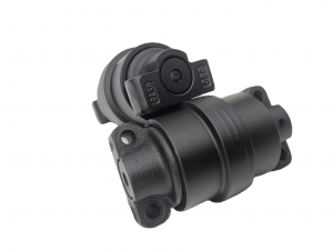
Construction Machinery Parts Excavator Undercar...
-

KTA0825/KSA14150/SUMITOMO-SH350/CX300 carrier r...


