
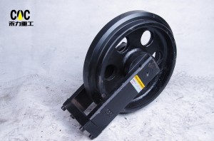
DOOSAN 27000049 22701084E DX300 S300LC Solar340 DX360LC-7 Track Front Idler Assembly / Heavy duty construction equipment parts Factory And Professional Undercarriage parts Manufacturer / CQC TRACK


Comprehensive Technical Analysis: DOOSAN 27000049 22701084E DX300 S300LC Solar340 DX360LC-7 Track Front Idler Assembly – Heavy Duty Construction Equipment Parts from CQC TRACK
Executive Summary
This technical publication delivers an exhaustive examination of the DOOSAN track front idler assembly—a mission-critical undercarriage component engineered for the DX300, S300LC, Solar340, and DX360LC-7 series heavy-duty hydraulic excavators. The part numbers 27000049 and 22701084E represent OEM specifications for Doosan’s 30-35 ton class machines, which are extensively deployed in heavy construction, infrastructure development, quarry operations, and demanding earthmoving applications worldwide.
The front idler assembly (alternatively designated as track adjuster idler, guide wheel, or tensioning idler) serves dual critical functions in excavator operation: it guides the track chain around the forward articulation point and provides the moving anchor point for the hydraulic track tensioning mechanism. For operators of Doosan’s 30-ton class machines, understanding the engineering principles, material specifications, and manufacturing quality indicators of this component is essential for making informed procurement decisions that optimize total cost of ownership in demanding applications.
This analysis examines the DOOSAN idler assembly through multiple technical lenses: functional anatomy, metallurgical composition for heavy-duty applications, advanced manufacturing process engineering, rigorous quality assurance protocols, and strategic sourcing considerations—with particular focus on CQC TRACK as a specialized manufacturer and supplier of heavy-duty construction equipment parts and professional undercarriage components operating from Quanzhou, China .
1. Product Identification and Technical Specifications
1.1 Component Nomenclature and Application
The DOOSAN track front idler assembly encompasses multiple OEM part numbers corresponding to specific excavator models within the 30-35 ton class. The primary part numbers addressed in this analysis include:
| OEM Part Number | Compatible Models | Machine Class | Application Notes |
|---|---|---|---|
| 27000049 | DX300, S300LC, Solar340 | 30-32 tons | Primary idler for standard configuration |
| 22701084E | DX300-7, DX360LC-7 | 32-35 tons | Enhanced heavy-duty variant |
These part numbers represent Doosan’s proprietary identification codes, corresponding to precise engineering drawings, dimensional tolerances, and material specifications developed through the original equipment manufacturer’s rigorous validation protocols.
The DX300, S300LC, Solar340, and DX360LC-7 series represent Doosan’s mid-size to large excavator lineup, with operating weights ranging from 30 to 35 tons, widely deployed in:
- Heavy construction: Major earthmoving, site development, infrastructure projects
- Quarry operations: Material handling, secondary breaking, stockpile management
- Infrastructure development: Road construction, bridge foundation, utility installation
- Demolition and recycling: Building demolition, material processing
- General contracting: Versatile applications across multiple job sites
1.2 Primary Functional Responsibilities
The front idler assembly in 30-35 ton class excavator applications performs three interconnected functions critical to machine performance and undercarriage longevity:
Track Guidance and Load Transfer: The idler’s peripheral surface contacts the track chain’s rail section, guiding the chain as it wraps around the forward articulation point. During forward travel, the idler experiences compressive forces; during reverse travel, it must withstand tensile loads transmitted through the chain. For 30-35 ton class machines with operating weights of 30,000-35,000 kg, static loads per idler typically range from 8,000-10,000 kg, with dynamic loads during excavation cycles reaching 2.5-3.5 times static values.
Track Tensioning Interface: The idler mounts on a sliding yoke connected to the track adjuster mechanism—typically a grease-filled hydraulic cylinder with relief valve. By moving the idler forward or backward, operators adjust track sag, maintaining optimal tension that balances wear reduction with mechanical efficiency. The adjustment stroke for 30-ton class excavator idlers typically ranges 100-150 mm.
Impact Load Management: During travel over uneven terrain, the idler absorbs and distributes initial contact shocks when the track chain rolls onto the undercarriage, protecting the track frame and final drive components from shock-induced damage. This function demands both exceptional structural strength and controlled deflection characteristics.
1.3 Technical Specifications and Dimensional Parameters
While Doosan’s exact engineering drawings remain proprietary, industry-standard specifications for 30-35 ton class excavator front idlers typically encompass the following parameters based on established manufacturing standards:
| Parameter | Typical Specification Range | CQC TRACK Achievement | Engineering Significance |
|---|---|---|---|
| Outer Diameter | 520-580 mm | ±0.10 mm tolerance | Determines contact radius with track links and wrap angle |
| Shaft Diameter | 80-95 mm | h6 tolerance (±0.015-0.025 mm) | Shear and bending capacity under combined loads |
| Flange Width | 110-130 mm | ±0.15 mm | Lateral stability and track guidance effectiveness |
| Flange Height | 22-28 mm | Controlled profile | Anti-derailment protection during side-slope operation |
| Flange Face Relief Angle | 8-12° | Precision-machined | Facilitates debris ejection, prevents material packing |
| Flange Root Radius | 8-12 mm | Optimized FEA design | Minimizes stress concentration, prevents crack initiation |
| Sliding Yoke Stroke | 100-150 mm | Full range verified | Range of track tension adjustment |
| Assembly Weight | 120-180 kg | Verified | Material content and structural robustness indicator |
| Bearing Configuration | Matched tapered roller bearings | Timken® / equivalent premium source | Accommodates combined radial and thrust loads |
| Material Specification | SAE 4140 / 50Mn / 40Cr | Premium certified alloy | Optimal balance of hardness and toughness |
| Core Hardness | 280-350 HB (29-38 HRC) | 100% verified | Toughness for impact absorption |
| Surface Hardness | HRC 58-62 | Induction hardened | Wear resistance for extended service life |
| Hardened Case Depth | 8-12 mm | Controlled gradient | Depth of wear-resistant layer for heavy-duty cycles |
| Tread Runout | ≤0.15 mm TIR | CMM verified | Vibration and track chain impact prevention |
| Concentricity | ≤0.10 mm | CMM verified | Smooth rotation and even wear distribution |
1.4 Component Anatomy and Design Architecture
The front idler assembly for Doosan DX300 series comprises several key components engineered for heavy-duty operation:
Idler Wheel: The main wheel that guides the track and maintains tension, featuring robust unitary construction with precision-machined tread surface and induction-hardened flange faces. The idler incorporates a substantially unitary disk-shaped web centered on the hub and extending radially outward to the outer rim, providing optimal load transfer between hub and rim while minimizing stress concentration.
Outer Rim Configuration: The outer rim is arranged proximate the outer cylindrical edge and extends laterally relative to the disk-shaped web. The rim features a raised portion flanked by a pair of lower ledges, with a cross-sectional profile precisely configured for engagement by the link assembly of the track system.
Shaft: The stationary axle manufactured from high-strength alloy steel with precision-ground bearing journals (h6 tolerance) and surface treatments for enhanced durability.
Bearing System: Matched sets of heavy-duty tapered roller bearings with dynamic load ratings appropriate for 30-35 ton class machines, featuring machined cages for superior shock load resistance and C3/C4 internal clearance for thermal expansion accommodation.
Sealing System: Multi-stage contamination barriers including primary floating seals (HRC 58-64, flatness ≤1.0 µm), secondary HNBR lip seals, and external labyrinth dust guards with multiple chambers.
Sliding Yoke: Robust steel forging designed to transmit tension loads while sliding smoothly on track frame rails, featuring induction-hardened sliding surfaces and replaceable wear plates.
Track Adjuster Interface: Precision-machined mounting surface for the track adjuster cylinder, ensuring proper alignment and load transfer.
2. Metallurgical Foundation: Material Science for Heavy-Duty Excavator Applications
2.1 Premium Alloy Steel Selection Criteria
The service environment of a 30-35 ton class excavator front idler presents demanding material requirements. The component must simultaneously:
- Resist abrasive wear from continuous contact with the track chain and exposure to soil, sand, rock, and construction debris
- Withstand impact loads from machine travel over rough terrain and dynamic loading during operation
- Maintain structural integrity under cyclic loading exceeding 10⁷ cycles over the machine’s lifetime
- Preserve dimensional stability despite exposure to temperature extremes, moisture, and chemical contaminants
Premium manufacturers like CQC TRACK select specific premium alloy steel grades that achieve the optimal balance of hardness, toughness, and fatigue resistance for heavy-duty excavator applications:
SAE 4140 / 42CrMo Chromium-Molybdenum Alloy: This is the preferred material for demanding excavator idlers. With carbon content of 0.38-0.45%, chromium of 0.90-1.20%, and molybdenum of 0.15-0.25%, SAE 4140 provides:
| Property | Typical Value | Engineering Significance |
|---|---|---|
| Ultimate Tensile Strength | 850-1000 MPa | Load-carrying capacity under extreme stress |
| Yield Strength | 700-850 MPa | Resistance to permanent deformation |
| Elongation | 12-16% | Ductility for impact absorption |
| Reduction of Area | 45-55% | Material quality indicator |
| Hardness (Q&T) | 280-350 HB | Core toughness for impact resistance |
| Impact Toughness (Charpy V-notch at -20°C) | 40-60 J | Low-temperature performance for cold climate operations |
50Mn Manganese Steel: For applications where enhanced wear resistance is prioritized, 50Mn with carbon 0.45-0.55% and manganese 1.4-1.8% provides:
- Excellent surface hardenability
- Good wear resistance from carbide formation
- Adequate toughness for most heavy-duty applications
- Cost-effectiveness for volume production
40Cr Chromium Alloy: For applications requiring enhanced hardenability and fatigue resistance, 40Cr (similar to AISI 5140) with carbon 0.37-0.44% and chromium 0.80-1.10% provides:
- Improved hardenability for uniform properties
- Enhanced fatigue strength from chromium carbides
- Good toughness at moderate hardness levels
- Excellent response to induction hardening
Material Traceability: Reputable manufacturers provide comprehensive material documentation, including Mill Test Reports (MTRs) certifying chemical composition with element-specific analysis (C, Si, Mn, P, S, Cr, Mo, Ni as applicable). Spectrographic analysis confirms alloy chemistry against certified specifications .
2.2 Forging vs. Casting: The Grain Structure Imperative
The primary forming method fundamentally determines the idler’s mechanical properties and service life. While casting offers cost advantages for simple geometries, it produces an equiaxed grain structure with random orientation, potential porosity, and inferior impact resistance. Premium excavator idler manufacturers exclusively employ closed-die hot forging for the idler wheel and yoke components.
The forging process for Doosan DX300 class components begins with cutting steel billets to precise weight, heating them to approximately 1150-1250°C until fully austenitized, then subjecting them to high-pressure deformation between precision-machined dies in hydraulic presses.
This thermo-mechanical treatment produces continuous grain flow that follows the component contour, aligning grain boundaries perpendicular to principal stress directions. The resulting structure exhibits:
| Property Improvement | Forged vs. Cast | Engineering Benefit |
|---|---|---|
| Fatigue Strength | +20-30% | Longer service life under cyclic loading |
| Impact Energy Absorption | +30-40% | Better resistance to shock loads |
| Structural Integrity | No porosity/inclusions | Elimination of failure initiation sites |
| Grain Orientation | Aligned with stress | Optimized load distribution |
| Density | 100% theoretical | Maximum material strength |
After forging, components undergo controlled cooling to prevent the formation of detrimental microstructures such as Widmanstätten ferrite or excessive grain boundary carbide precipitation.
2.3 Dual-Property Heat Treatment Engineering for Heavy-Duty Components
The metallurgical sophistication of a quality heavy-duty idler manifests in its precisely engineered hardness profile—an extremely hard, wear-resistant surface coupled with a tough, impact-absorbing core:
Quenching and Tempering (Q&T) : The entire forged idler body is austenitized at 840-880°C, then rapidly quenched in agitated water, oil, or polymer solution. This transformation produces martensite—providing maximum hardness but with associated brittleness. Immediate tempering at 500-650°C allows carbon to precipitate as fine carbides, relieving internal stresses and restoring toughness. The resulting core hardness typically ranges from 280-350 HB (29-38 HRC), providing optimal toughness for impact absorption in heavy-duty excavator applications.
Induction Surface Hardening: Following finish machining, the critical wear surfaces—specifically the tread diameter and flange faces—undergo localized induction hardening. A precision-designed multi-turn copper inductor coil surrounds the component, inducing eddy currents that rapidly heat the surface layer to austenitizing temperature (900-950°C) within seconds. Immediate water quenching produces a martensitic case of 8-12 mm depth with surface hardness of HRC 58-62, providing exceptional resistance to abrasive wear from track chain contact in demanding applications.
Hardness Profile Verification: Quality manufacturers perform microhardness traverses on sample components to verify case depth compliance with specifications. The hardness gradient from surface through the hardened case to the core must follow a controlled transition to prevent spalling or case-core separation under impact loading. A typical hardness profile shows:
| Depth from Surface | Hardness Range | Microstructure |
|---|---|---|
| 0-2 mm | HRC 58-62 | Tempered martensite |
| 2-4 mm | HRC 55-58 | Tempered martensite |
| 4-6 mm | HRC 50-55 | Tempered martensite/bainite |
| 6-8 mm | HRC 45-50 | Bainite/martensite |
| 8-10 mm | HRC 35-45 | Bainite/ferrite |
| Core (>10 mm) | 280-350 HB | Tempered martensite/bainite |
2.4 Comprehensive Quality Assurance Protocols
Manufacturers like CQC TRACK implement multi-stage quality verification throughout production, with enhanced protocols for heavy-duty excavator components :
- Spectroscopic Material Analysis: Confirms alloy chemistry against certified specifications at raw material receipt, with enhanced element verification for critical alloys. Chemistry must meet strict limits for all elements, particularly carbon (±0.03%), manganese (±0.05%), and chromium (±0.05%).
- Ultrasonic Testing (UT) : 100% inspection of critical forgings verifies internal soundness, detecting any centerline porosity, inclusions, or laminations that could compromise structural integrity under heavy loads. Testing follows ASTM A388 or equivalent standards.
- Hardness Verification: Rockwell or Brinell hardness testing confirms both core hardness after Q&T treatment and surface hardness after induction hardening. Enhanced sampling rates for heavy-duty components (up to 100% for critical features) with full documentation.
- Magnetic Particle Inspection (MPI) : Examines critical areas—particularly flange roots, shaft transitions, and fillet radii—detecting any surface-breaking cracks or grinding burns with enhanced sensitivity. Testing follows ASTM E709 or equivalent standards.
- Dimensional Verification: Coordinate Measuring Machines (CMM) verify critical dimensions, with statistical process control maintaining process capability indices (Cpk) exceeding 1.33 for critical features. Full dimensional reports are provided with each shipment.
- Mechanical Testing: Sample components undergo tensile testing and impact testing (Charpy V-notch) at reduced temperatures to verify toughness for cold-climate operations.
- Microstructural Evaluation: Metallographic examination verifies proper grain structure, case depth, martensitic structure, and absence of detrimental phases.
- Running Test Validation: Assembled idlers undergo running tests that simulate actual operating conditions, monitoring temperature rise, vibration spectra, and noise levels to verify performance before shipment.
3. Precision Engineering: Component Design and Manufacturing
3.1 Idler Rim Geometry Optimization for Doosan Excavators
The idler rim geometry for Doosan DX300 class machines must precisely match the track chain specifications while accommodating the loads of heavy-duty operation:
Outer Diameter: The 520-580 mm diameter is calculated to provide appropriate rotational speed and bearing L10 life at typical travel speeds (2-4 km/h). The diameter must be maintained within tight tolerances (±0.10 mm) to ensure consistent chain support height and proper wrap angle (typically 100-120°).
Tread Profile Design: The contact surface incorporates an optimized crown profile (typically 0.5-1.5 mm radius) to accommodate minor track misalignment and prevent edge loading that could accelerate localized wear. The profile is developed through finite element analysis to ensure uniform pressure distribution across the contact patch under varying load conditions. Key design parameters include:
| Tread Parameter | Specification | Engineering Significance |
|---|---|---|
| Crown Radius | 0.5-1.5 mm | Accommodates misalignment, prevents edge loading |
| Surface Roughness (Ra) | ≤1.6 µm | Optimizes wear characteristics with track bushings |
| Profile Tolerance | ±0.10 mm | Ensures consistent chain engagement |
| Hardness Transition | Controlled gradient | Prevents spalling under impact |
Flange Geometry: Front idlers for Doosan excavators feature robust double-flange designs that provide positive track retention in both directions—essential for operation on side slopes and uneven terrain. Critical flange design elements include:
| Flange Feature | Specification | Engineering Significance |
|---|---|---|
| Flange Height | 22-28 mm | Provides robust lateral constraint to prevent derailment |
| Flange Width (radial thickness) | 20-30 mm | Ensures adequate strength for anti-derailment function |
| Flange Face Relief Angle | 8-12° | Facilitates debris ejection, prevents material packing |
| Flange Root Radius | 8-12 mm | Minimizes stress concentration, prevents crack initiation |
| Flange Face Hardness | HRC 58-62 | Wear resistance against track link sidebars |
| Flange-to-Flange Distance | 120-150 mm | Accommodates track link width with 4-8 mm clearance |
Disk-Shaped Web Design: The idler incorporates a substantially unitary disk-shaped web centered on the hub and extending radially outward to the outer rim. This design provides optimal load transfer between the hub and rim while minimizing weight and stress concentration.
3.2 Shaft and Bearing System Engineering
The stationary shaft must withstand continuous bending moments and shear stresses while maintaining precise alignment with the rotating idler body. For Doosan DX300 applications, shaft diameters typically range 80-95 mm, calculated based on:
- Static machine weight distributed to the front idler (approximately 25-30% of front-end weight)
- Dynamic load factors of 2.5-3.5 for heavy-duty applications
- Track tension loads that can exceed 15 tonnes during operation
- Side loads during turning and slope operation (up to 30-40% of vertical load)
The bearing system for Doosan excavator front idlers employs matched sets of heavy-duty tapered roller bearings, specifically selected for heavy-duty applications:
| Bearing Parameter | Specification | Engineering Significance |
|---|---|---|
| Bearing Type | Matched tapered roller bearings (double row) | Simultaneously supports high radial and thrust loads |
| Dynamic Load Rating (C) | 400-600 kN | Appropriate for 30-35 ton class machines |
| Static Load Rating (C0) | 600-900 kN | Withstands peak impact loads without permanent deformation |
| Cage Design | Machined brass cage | Superior strength for shock loading compared to stamped steel |
| Internal Clearance | C3 or C4 class | Accommodates thermal expansion during operation |
| Raceway Finish | Super-finished (Ra ≤0.1 µm) | Reduces friction, extends fatigue life |
| Roller Profile | Optimized crowning | Prevents edge loading under misalignment |
| Material | Case-hardened bearing steel | Maximum surface durability with tough core |
Premium manufacturers source bearings from reputable suppliers such as Timken®, NTN, KOYO, SKF, or equivalent high-quality bearing manufacturers with proven performance in heavy-duty applications.
The shaft bearing journals are precision-ground to h6 tolerance (±0.015-0.025 mm) and surface-treated (e.g., chrome plating, nitriding, or induction hardening) for enhanced wear resistance and corrosion protection.
3.3 Advanced Multi-Stage Sealing Technology
The seal system is the single most critical determinant of idler longevity in heavy-duty excavator applications, where machines operate in environments with significant contamination levels. Industry data indicates that the majority of premature idler failures originate from seal compromise.
Premium heavy-duty excavator front idlers from CQC TRACK employ multi-stage sealing systems specifically engineered for contaminated environments:
Primary Heavy-Duty Floating Seal: Precision-ground hardened iron or steel rings with lapped sealing faces achieving flatness within 0.5-1.0 µm. For heavy-duty applications, seal face materials and coatings are selected for:
| Seal Feature | Specification | Benefit |
|---|---|---|
| Seal Ring Material | Through-hardened steel or special iron alloy (HRC 58-64) | Maximum wear resistance |
| Seal Face Flatness | ≤1.0 µm | Maintains continuous contact, prevents leakage |
| Seal Face Roughness | Ra ≤0.1 µm | Minimizes friction, extends life |
| Seal Face Coating | Optional enhanced coatings | Additional wear resistance for extreme conditions |
| Seal Ring Hardness | HRC 58-64 | Resists abrasive wear from contaminants |
Secondary Radial Lip Seal: Manufactured from premium elastomer materials with:
- HNBR (Hydrogenated Nitrile Butadiene Rubber) : Exceptional temperature resistance (-40°C to +150°C), chemical compatibility with EP greases, enhanced abrasion resistance
- Positive sealing pressure maintained by garter spring (stainless steel for corrosion resistance)
- Dust lip integrated design to exclude coarse contaminants
External Labyrinth-Style Dust Guard: Creates a tortuous path with multiple chambers that progressively trap coarse contaminants before they reach the primary seals. The labyrinth is:
- Packed with high-adhesion, extreme-pressure grease
- Designed with expulsion channels for self-cleaning action during rotation
- Configured with multiple stages (typically 3-5 chambers) for maximum protection
Grease Cavity: An intermediate cavity packed with EP grease that acts as a barrier, expelling any potential contaminants that bypass the outer seals.
Pre-Lubrication: The bearing cavity is pre-filled with heavy-duty, extreme pressure (EP) grease containing:
- Molybdenum disulfide (MoS₂) or graphite for boundary lubrication
- Enhanced anti-wear additives for shock load protection
- Corrosion inhibitors for wet environment operation
- Oxidation stabilizers for extended service intervals
3.4 Sliding Yoke and Track Tensioning Interface Engineering
The sliding yoke houses the idler shaft and connects to the track adjuster cylinder. For Doosan DX300 applications, the yoke is a robust steel forging designed to transmit tension loads while sliding smoothly on the track frame rails.
Critical design features include:
| Yoke Component | Specification | Engineering Significance |
|---|---|---|
| Yoke Material | Forged alloy steel | Maximum strength and fatigue resistance |
| Hardened Wear Plates | Induction-hardened or replaceable inserts | Sacrificial components protect main yoke |
| Sliding Surface Finish | Ra ≤1.6 µm | Smooth operation, reduced friction |
| Grease Fittings | Zerk fittings with check valves | Scheduled re-lubrication capability |
| Adjuster Mounting Surface | Precision-machined (±0.05 mm flatness) | Proper alignment with track adjuster cylinder |
| Structural Analysis | FEA-optimized | Minimizes stress concentration, weight optimization |
The interface with the track adjuster utilizes a hydraulic tensioning system: grease is pumped into a cylinder behind the yoke, pushing the idler forward and tensioning the track. A relief valve prevents over-tensioning.
3.5 Precision Machining and Quality Control
Modern CNC machining centers achieve dimensional tolerances that directly correlate with service life in heavy-duty excavator applications. Critical parameters for Doosan DX300 class idlers include:
| Feature | Typical Tolerance | Measurement Method | Consequence of Deviation |
|---|---|---|---|
| Shaft Journal Diameter | h6 to h7 (±0.015-0.025 mm) | Micrometer (0.001 mm resolution) | Clearance affects lubrication film and load distribution |
| Bearing Bore Diameter | H7 to H8 (±0.020-0.035 mm) | Bore gauge / CMM | Fit with bearing outer race; incorrect fit causes premature bearing failure |
| Seal Housing Bore | H8 to H9 (±0.025-0.045 mm) | Bore gauge / CMM | Seal compression affects sealing force and life |
| Tread Diameter | ±0.10 mm | Micrometer / CMM | Consistent chain support and wrap angle |
| Flange-to-Flange Distance | ±0.15 mm | CMM | Proper track link engagement and guidance |
| Flange Parallelism | ≤0.05 mm across diameter | CMM | Misalignment induces uneven wear and side loading |
| Tread Runout | ≤0.15 mm total indicated | Dial indicator / CMM | Vibration and track chain impact |
| Concentricity | ≤0.10 mm | CMM | Smooth rotation and even wear distribution |
| Surface Finish (tread) | Ra ≤1.6 µm | Profilometer | Wear rate and chain interaction |
| Surface Finish (bearing journals) | Ra ≤0.4 µm | Profilometer | Bearing life and lubrication |
| Surface Finish (seal areas) | Ra ≤0.4 µm | Profilometer | Seal wear rate and leakage prevention |
CNC-controlled turning and grinding processes guarantee precise geometry and surface finish for smooth track chain interaction. In-process dimensional verification with real-time feedback to machine operators enables immediate correction of process drift.
3.6 Assembly and Pre-Delivery Testing Protocols
Final assembly is performed in controlled conditions to prevent contamination—a critical requirement for components where even microscopic contaminants can initiate premature wear. Assembly protocols include:
- Component Cleaning: Thorough cleaning of all components before assembly using specialized cleaning solutions that remove all machining residues, oils, and particulates.
- Controlled Environment: Clean assembly areas with contamination control and temperature/humidity management.
- Bearing Installation: Precision pressing with force monitoring to ensure proper seating; bearings may be heated for expansion to facilitate installation without damage.
- Preload Setting: Tapered roller bearings are adjusted to specified preload using specialized fixtures and torque measurement.
- Seal Installation: Specialized tools prevent damage to sealing lips and faces; seal faces are lubricated during installation with assembly grease.
- Lubrication: Measured grease fill with specified heavy-duty lubricants; air pockets are eliminated during filling.
- Rotation Testing: Verification of smooth rotation and correct bearing preload.
Pre-delivery testing for heavy-duty excavator idlers includes:
- Rotational torque test to verify smooth rotation and correct bearing preload
- Seal integrity test with pressurized air and soap solution to detect leakage paths
- Dimensional inspection of the assembled unit to verify all critical fits
- Visual inspection of seal installation, fastener torque, and overall workmanship
- Running test on sample basis to verify performance under simulated loads
4. CQC TRACK: Professional Undercarriage Parts Manufacturer
4.1 Company Overview and Industry Position
CQC TRACK (operating under HELI Group affiliation) is a specialized industrial manufacturer and supplier of heavy-duty undercarriage systems and chassis components, operating on both ODM and OEM principles. Based in Quanzhou, Fujian Province—a region recognized for specialized expertise in customized undercarriage solutions—the company has established itself as a significant player in the global undercarriage components market, with particular strength in excavator components for construction and mining applications .
With specialized focus on undercarriage components for global markets, CQC TRACK has developed comprehensive capabilities across the entire undercarriage product spectrum, including track rollers, carrier rollers, front idlers, sprockets, track chains, and track shoes for applications ranging from mini excavators to large mining-class machines. The company serves as a source factory and manufacturer for heavy-duty construction equipment parts, supplying international distributors, equipment dealers, and aftermarket networks worldwide.
4.2 Technical Capabilities and Engineering Expertise
Integrated Heavy-Duty Manufacturing: CQC TRACK controls the full production cycle from material sourcing and forging to precision machining, heat treatment, assembly, and quality testing. For Doosan DX300 class components, this vertical integration ensures consistent quality and complete traceability throughout the manufacturing process .
Advanced Metallurgical Expertise: The company’s technical team leverages advanced metallurgical knowledge and dynamic load simulation tools to design components for heavy-duty excavator applications. For Doosan idlers, this includes:
- Material Selection: Premium SAE 4140, 50Mn, and 40Cr alloy steels with certified chemistry
- Heat Treatment: Quenched and tempered to core hardness 280-350 HB, followed by induction hardening to surface HRC 58-62 with case depth 8-12 mm
- Finite Element Analysis (FEA) : Stress distribution analysis under operational loads to optimize geometry and minimize stress concentration
- Fatigue Life Prediction: Based on heavy-duty duty cycle data
Quality Assurance Protocols: Production is governed by a Quality Management System (QMS) aligned with international standards (ISO 9001). Each batch undergoes rigorous inspection, including material analysis, dimensional verification, and performance testing .
Engineering Support: The company’s engineering team provides technical support for application verification, ensuring correct part selection for specific Doosan models and production years. Their expertise lies in reverse-engineering and manufacturing aftermarket parts that meet or exceed original equipment performance.
4.3 Product Range for Doosan Excavators
CQC TRACK manufactures a comprehensive range of undercarriage components for Doosan excavators, including:
| Component Type | Compatible Models | Doosan Part Numbers |
|---|---|---|
| Front Idler Assembly | DX300, S300LC, Solar340, DX360LC-7 | 27000049, 22701084E |
| Track Roller (Bottom Roller) | DX300 series | Various |
| Carrier Roller (Upper Roller) | DX300 series | Various |
| Sprocket / Drive Segment | DX300 series | Various |
| Track Chain Assembly | DX300 series | Various pitches |
| Track Shoes | DX300 series | Various widths |
The company maintains tooling and production capability for multiple Doosan excavator models, ensuring consistent supply for both current production and field support requirements.
4.4 Global Supply Capability
CQC TRACK serves international markets with particular attention to major construction and infrastructure development regions worldwide. With production facilities in Quanzhou, the company offers:
- Competitive lead times: Typically 35-55 days for custom production
- Flexible minimum order quantities: Suitable for both small dealers and large contractors
- Emergency response capability: Expedited production for critical downtime situations
- Technical field support: Engineering consultation for application optimization
- Inventory programs: Stocking arrangements for high-demand components
5. Doosan DX300 Series Overview
5.1 Machine Classification and Applications
The Doosan DX300, S300LC, Solar340, and DX360LC-7 series represent Doosan’s mid-size to large excavator lineup, designed for heavy-duty construction and infrastructure applications worldwide:
| Model | Operating Weight | Engine Power | Typical Applications |
|---|---|---|---|
| DX300 / S300LC | 30-32 tons | 180-210 kW | Heavy construction, infrastructure, quarry operations |
| Solar340 | 32-33 tons | 200-220 kW | General construction, material handling |
| DX360LC-7 | 34-35 tons | 220-240 kW | Heavy construction, large-scale earthmoving |
These machines feature:
- Heavy-duty undercarriage systems designed for extended service life in demanding conditions
- High-quality components throughout, including front idlers engineered for durability
- Advanced hydraulic systems for maximum productivity and efficiency
- Operator-focused cabs with comprehensive monitoring and control systems
- Global service support through Doosan’s worldwide dealer network
5.2 Undercarriage System Specifications
The undercarriage system for Doosan DX300 class machines represents robust track design:
| Component | Typical Specification | Features |
|---|---|---|
| Track Chain Pitch | 190-216 mm | Sealed and lubricated design |
| Track Shoe Width | 600-900 mm | Multiple widths for ground pressure optimization |
| Number of Track Rollers | 7-9 per side | Sealed rollers with dual-flange configuration |
| Number of Carrier Rollers | 2-3 per side | Upper rollers with enhanced seals |
| Track Gauge | 2,500-2,800 mm | Wide stance for stability |
| Ground Pressure | 50-80 kPa | Optimized for varied ground conditions |
The front idler in this system must withstand substantial loads from track tension and dynamic loading during operation.
5.3 Construction Duty Cycle Considerations
Front idlers in heavy construction applications experience demanding duty cycles:
- Continuous operation: Often 10-12 hours per day, 5-6 days per week
- Varied terrain: Operation on rough construction sites, unimproved roads
- Material handling: Excavation of various soil and rock types
- Temperature ranges: From freezing to hot summer conditions
- Contamination: Exposure to dust, mud, water, and construction debris
- Impact loading: Travel over uneven ground and obstacles
These conditions demand front idlers with robust specifications, quality sealing, and reliable performance.
5.4 Part Number Cross-Reference and Interchangeability
Understanding part number relationships is essential for accurate sourcing:
| Part Number | Application | Notes |
|---|---|---|
| 27000049 | DX300, S300LC, Solar340 | Standard configuration for 30-32 ton models |
| 22701084E | DX300-7, DX360LC-7 | Enhanced variant for newer series and heavy-duty applications |
Both part numbers refer to front idler assemblies that may be interchangeable depending on specific machine configuration and production year. Verification against machine serial numbers is recommended for precise compatibility.
6. Performance Validation and Service Life Expectations
6.1 Benchmarks for 30-35 Ton Class Excavator Front Idlers
Field data from diverse operating environments provides realistic performance expectations for Doosan DX300 class front idlers:
| Application Severity | Operating Environment | Expected Service Life |
|---|---|---|
| General Construction | Mixed terrain, moderate conditions | 5,000-7,000 hours |
| Heavy Construction | Major earthmoving, varied terrain | 4,500-6,000 hours |
| Quarry Operations | Continuous operation, moderate abrasion | 4,000-5,500 hours |
| Infrastructure | Highway/development projects | 4,500-6,500 hours |
Research indicates that undercarriage parts can represent over 30% of total equipment maintenance costs, making component quality and longevity critical factors in total cost of ownership .
Premium aftermarket front idlers from reputable manufacturers like CQC TRACK demonstrate performance parity with OEM heavy-duty components, achieving 85-95% of OEM service life at significantly lower acquisition cost (typically 30-50% below OEM pricing). Parts made from high-quality materials can last 20-30% longer than cheaper alternatives, translating into significant long-term savings .
6.2 Common Failure Modes in Heavy-Duty Applications
Understanding failure mechanisms enables proactive maintenance and informed procurement decisions:
Seal Failure and Contamination Ingress: The predominant failure mode in heavy-duty applications, seal compromise allows abrasive particles to enter the bearing cavity. Initial symptoms include:
- Grease leakage around seals (visible as wetness or accumulated debris)
- Increasing operating temperature (detectable by infrared thermography)
- Rough rotation as contamination initiates bearing wear
- Progressive increase in running torque
- Eventually, seizure or catastrophic bearing failure
Flange Wear: Progressive wear on flange faces indicates inadequate surface hardness or improper track alignment. In heavy-duty applications, this can be accelerated by:
- Frequent operation on side slopes
- Tight turning on abrasive surfaces
- Track misalignment from worn components
- Impact damage from debris
Critical wear indicators include thinning of flange width (reducing lateral constraint) and development of sharp edges (increasing stress concentration).
Tread Wear and Diameter Reduction: The idler tread gradually wears from continuous contact with track bushings. When tread diameter reduction exceeds specifications (typically 10-15 mm), several consequences occur:
| Consequence | Effect | Resulting Damage |
|---|---|---|
| Reduced chain support height | Altered engagement geometry | Accelerated chain and idler wear |
| Increased contact pressure | Reduced contact area | Faster wear progression |
| Decreased wrap angle | Reduced chain guidance | Potential for chain jumping |
| Increased dynamic loading | Chain slapping | Accelerated seal and bearing wear |
Bearing Fatigue: After extended service, bearings may exhibit spalling due to subsurface fatigue, indicating the component has reached its natural life limit. Often accelerated by:
- Higher-than-expected dynamic loading
- Contamination-induced surface distress from seal breaches
- Lubricant degradation from high operating temperatures
- Misalignment from frame deflection
Shaft Fatigue: In severe applications with repetitive high-impact loading, shaft fatigue cracks may develop at stress concentration points.
6.3 Wear Indicators and Inspection Protocols
Regular inspection at 250-hour intervals should check for:
- Seal condition: Grease leakage, debris accumulation around seals, seal damage
- Idler rotation: Smoothness, noise, binding, rotational resistance
- Operating temperature: Comparison with baseline using infrared thermometer
- Flange condition: Wear measurement, sharp edges, damage, cracks
- Tread condition: Wear pattern analysis, diameter measurement, surface damage
- Yoke movement: Smooth sliding, clearance, lubrication condition
- Track adjuster function: Proper operation, no leakage
- Mounting integrity: Fastener torque, bracket condition, alignment
- Radial play: Vertical movement detection
- Axial play: Lateral movement detection
- Unusual noises: Grinding, squeaking, knocking during operation
Implementing a regular maintenance schedule can extend equipment life and prevent unexpected breakdowns .
7. Installation, Maintenance, and Service Life Optimization
7.1 Professional Installation Practices for Doosan Excavators
Proper installation significantly impacts idler service life in Doosan DX300 class machines:
Track Frame Preparation: The sliding surfaces of the track frame must be clean, flat, and free of burrs, corrosion, or damage. Critical steps include:
- Thorough cleaning of sliding surfaces and bolt holes
- Inspection for cracks or damage around mounting areas
- Measurement of sliding surface flatness
- Inspection and replacement of worn wear plates or liners
- Verification of track frame alignment
Yoke and Track Adjuster Inspection: The yoke should slide freely on the frame rails; apply grease to sliding surfaces as recommended. The track adjuster cylinder should be inspected for damage, leakage, and proper operation.
Fastener Specifications: All mounting bolts must be:
- Grade 10.9 or 12.9 as specified
- Clean and lightly oiled before installation
- Tightened in proper sequence to specified torque using calibrated torque wrenches
- Equipped with appropriate locking features
- Marked after torquing for visual inspection
- Retorqued after initial operation (typically 50-100 hours)
Alignment Verification: After installation, verify that:
- The idler is properly aligned with the track chain path
- The idler contacts the track chain evenly across its width
- Flange clearances to track links are within specification
- The idler rotates freely without binding or interference
- The yoke moves smoothly through its adjustment range
Track Tension Adjustment: After installation, adjust track tension according to machine specifications. For 30-35 ton class excavators, proper sag typically ranges 30-50 mm measured at the center of the lower track run between the front idler and first track roller.
7.2 Preventive Maintenance Protocols
Regular Inspection Intervals: Visual inspection at 250-hour intervals should check for all wear indicators previously described. More frequent inspection (daily walk-around) should include visual check for obvious seal leakage or damage.
Track Tension Management: Proper track tension directly impacts idler life. Excessive tension increases bearing loads; insufficient tension allows chain slapping that accelerates seal deterioration and increases impact loads. Check tension:
- At every 250-hour service interval
- After the first 10 hours on new components
- When operating conditions change significantly
- When abnormal track behavior is observed
Cleaning Protocols: In heavy-duty environments, proper cleaning is essential but must be performed correctly:
- Avoid high-pressure washing directed at seal areas
- Use low-pressure water for general cleaning
- Remove accumulated debris during daily inspections
- Allow components to dry thoroughly
Lubrication: For idlers with sealed bearings, no additional lubrication is required during service life. For yoke sliding surfaces and track adjuster:
- Use specified heavy-duty greases with appropriate additives
- Follow recommended intervals and quantities
- Wipe fittings clean before and after lubrication
- Record lubrication history
Operating Practice Considerations: Operator practices significantly impact idler life:
- Minimize high-speed travel over rough terrain
- Avoid sudden direction changes that impose high side loads
- Keep track tension properly adjusted for conditions
- Report unusual noises or handling immediately
- Avoid operation with severely worn track components
7.3 Replacement Decision Criteria
Front idlers for Doosan DX300 class machines should be replaced when:
- Seal leakage is evident and cannot be stopped
- Radial play exceeds manufacturer specifications (typically 3-5 mm)
- Axial play exceeds manufacturer specifications (typically 2-4 mm)
- Flange wear reduces guidance effectiveness (thickness reduction exceeding 25%)
- Flange damage includes cracks, spalling, or severe deformation
- Tread wear exceeds hardened case depth (diameter reduction exceeding 10-15 mm)
- Surface spalling affects more than 10% of contact area
- Bearing rotation becomes rough, noisy, or irregular
- Operating temperature consistently elevated
- Visible damage includes cracks or deformation
- Yoke wear prevents proper sliding or alignment
7.4 System-Based Replacement Strategy
For optimal undercarriage performance and cost efficiency, the idler condition should be evaluated alongside:
- Track chain: Pin and bushing wear, rail condition, overall elongation
- Track rollers: Seal condition, tread wear, bearing condition across all rollers
- Carrier rollers: Tread condition, bearing condition
- Sprocket: Tooth wear profile, segment condition, mounting integrity
- Track frame: Alignment, wear plate condition
Industry best practice recommends:
- Replace in pairs: Idlers on both sides together
- Consider system replacement: When multiple components show significant wear
- Schedule during major service: Plan during scheduled downtime
8. Strategic Sourcing Considerations
8.1 The OEM vs. Aftermarket Decision
Equipment managers must evaluate the OEM versus high-quality aftermarket decision through multiple lenses:
Cost Analysis: Aftermarket components from manufacturers like CQC TRACK typically offer 30-50% initial cost savings compared to OEM parts. For fleets with multiple Doosan DX300 class machines, this differential can represent significant annual savings. Total cost of ownership calculations must factor in:
- Expected service life in specific operating conditions
- Maintenance labor costs for replacement
- Production downtime impact
- Warranty coverage
- Parts availability and lead times
Research indicates that over 40% of operators prefer aftermarket parts for their cost-effectiveness .
Quality Parity: Premium aftermarket manufacturers achieve performance parity with OEM heavy-duty components through:
- Equivalent material specifications (SAE 4140/50Mn with certified chemistry)
- Comparable heat treatment processes (core 280-350 HB, surface HRC 58-62, case depth 8-12 mm)
- Heavy-duty sealing systems with multi-stage contamination protection
- Matched bearing sets from reputable bearing manufacturers
- Rigorous quality control with comprehensive testing
Warranty Considerations: OEM warranties typically cover 1-2 years or 2,000-3,000 hours. Reputable aftermarket manufacturers offer comparable warranties covering manufacturing defects, with coverage periods of 1-2 years.
Availability and Lead Times: OEM parts may face extended lead times due to centralized distribution. Aftermarket manufacturers with local production often deliver within 4-8 weeks, with emergency expediting available for critical situations.
Technical Support: Aftermarket suppliers with engineering expertise can provide:
- Application engineering support
- Field service support for installation
- Component life data for maintenance planning
- Failure analysis services
8.2 Supplier Evaluation Criteria
Procurement professionals should apply rigorous evaluation frameworks when assessing potential front idler suppliers:
Manufacturing Capability Assessment: Facility evaluations should verify the presence of:
- Forging equipment for heavy-duty components
- CNC machining centers with precision capabilities
- Heat treatment facilities with atmosphere control
- Induction hardening stations with process monitoring
- Clean assembly areas for seal installation
- Testing facilities (UT, MPI, CMM, metallurgical laboratory)
Quality Management Systems: ISO 9001:2015 certification represents minimum acceptable standard.
Material and Process Transparency: Reputable manufacturers readily provide:
- Material certifications (MTRs) with full chemistry
- Heat treatment process documentation
- Inspection reports for dimensional verification and NDT
- Sample testing capability
Experience and Reputation: Suppliers with extensive experience demonstrate sustained capability. Quality and durability should be prioritized when selecting suppliers .
Financial Stability: Long-term supply relationships require financially stable partners.
8.3 The CQC TRACK Advantage for Doosan Applications
CQC TRACK offers several distinct advantages for Doosan excavator undercarriage procurement:
- Heavy-Duty Manufacturing Capability: Components engineered specifically for demanding construction applications
- Integrated Production Control: Full vertical integration ensures consistent quality and traceability
- Material Excellence: Premium alloy steels (SAE 4140, 50Mn, 40Cr) with controlled chemistry
- Advanced Sealing: Multi-stage sealing systems for contamination protection
- Comprehensive Quality Assurance: Rigorous testing protocols and ISO 9001 certification
- Application Expertise: Technical team with understanding of Doosan undercarriage systems
- Global Supply Capability: Reliable lead times and competitive pricing
- Competitive Economics: 30-50% cost savings while maintaining heavy-duty quality
- Engineering Support: Customization capabilities for specific operating conditions
9. Market Analysis and Future Trends
9.1 Global Demand Patterns
The global market for excavator undercarriage components continues expanding, driven by:
Construction Industry Growth: Increasing construction activity worldwide drives demand for heavy equipment and replacement parts. The excavator undercarriage components market is projected to reach approximately $5 billion by 2027 .
Infrastructure Development: Major infrastructure initiatives across Asia-Pacific, Middle East, Africa, and South America sustain demand for heavy equipment and replacement parts. Asia-Pacific leads the market due to rapid urbanization and infrastructure investment .
Equipment Fleet Aging: Extended equipment retention periods increase aftermarket parts consumption.
Geographic Trends: Countries like China and India are investing heavily in infrastructure, creating increased need for robust undercarriage solutions .
9.2 Technological Advancements
Emerging technologies are transforming undercarriage component manufacturing:
Advanced Materials Development: Research into enhanced steel alloys and innovative rubber compounds promises improved wear resistance. High-strength steel and advanced materials enhance component lifespan and contribute to lower operational costs .
Induction Hardening Optimization: Advanced systems achieve unprecedented uniformity in case depth and hardness distribution.
Automated Assembly and Inspection: Robotic systems ensure consistent seal installation and dimensional verification.
Predictive Maintenance Technologies: Sensors are increasingly used to monitor wear and alert operators to necessary maintenance. Predictive maintenance can reduce operational costs by up to 15% .
Sustainability Focus: Manufacturers are exploring eco-friendly materials and recycling options .
9.3 Challenges and Considerations
The market faces several challenges:
- Fluctuating raw material prices affecting component costs
- Supply chain issues impacting availability
- Quality variation among manufacturers requiring careful supplier selection
- Transition to smart systems requiring initial investment and compatibility considerations
10. Conclusion and Strategic Recommendations
The DOOSAN 27000049 and 22701084E track front idler assembly for DX300, S300LC, Solar340, and DX360LC-7 excavators represents a precision-engineered heavy-duty component whose performance directly impacts machine availability, operating cost, and project profitability. Understanding the technical intricacies—from alloy selection (SAE 4140/50Mn/40Cr) and forging methodology through precision machining, bearing systems, and multi-stage seal design—enables equipment managers to make informed procurement decisions that balance initial cost against total cost of ownership.
For heavy equipment operators utilizing Doosan 30-35 ton class excavators, the following strategic recommendations emerge:
- Prioritize heavy-duty specifications, verifying material grades, heat treatment parameters, and seal system design for construction environments.
- Verify sealing system robustness, recognizing that multi-stage seals with floating seals, HNBR lip seals, and labyrinth dust guards provide essential protection.
- Evaluate suppliers through capability lens, seeking evidence of forging capacity, modern CNC equipment, heat treatment capability, and comprehensive testing facilities.
- Demand material and process transparency, requesting material certifications, heat treatment records, and inspection reports.
- Confirm cross-reference accuracy when substituting aftermarket components for OEM part numbers 27000049 and 22701084E.
- Implement appropriate maintenance protocols, including regular inspection for seal condition, tread wear, and flange integrity.
- Adopt system-based replacement strategies, evaluating idler condition alongside track chain, rollers, and sprocket.
- Develop strategic supplier partnerships with manufacturers like CQC TRACK that demonstrate technical competence, quality commitment, and supply chain reliability .
- Consider total cost of ownership, evaluating aftermarket options that offer 30-50% cost savings while maintaining heavy-duty quality and performance parity with OEM components.
- Establish component life tracking to develop site-specific performance data for predictive replacement planning.
By applying these principles, equipment operators can secure reliable, cost-effective undercarriage solutions that maintain excavator productivity while optimizing long-term operational economics.
CQC TRACK, as a specialized manufacturer with integrated production capabilities and comprehensive quality assurance for heavy-duty applications, represents a viable source for Doosan DX300 series idler assemblies, offering professional quality with the cost advantages of specialized manufacturing.
Frequently Asked Questions (FAQ)
Q: What is the typical service life of a Doosan 27000049 front idler on DX300 class excavators?
A: Service life varies with operating conditions: general construction 5,000-7,000 hours, heavy construction 4,500-6,000 hours, quarry operations 4,000-5,500 hours, infrastructure projects 4,500-6,500 hours.
Q: How can I verify that an aftermarket front idler meets Doosan specifications?
A: Request material test reports (MTRs) certifying alloy chemistry (SAE 4140/50Mn), hardness verification documentation (core 280-350 HB, surface HRC 58-62, case depth 8-12 mm), and dimensional inspection reports. Reputable manufacturers like CQC TRACK readily provide this documentation.
Q: What are the differences between Doosan part numbers 27000049 and 22701084E?
A: 27000049 is the primary idler for standard DX300, S300LC, and Solar340 models. 22701084E is an enhanced variant for DX300-7 and DX360LC-7 series, typically featuring upgraded specifications for heavy-duty applications.
Q: What distinguishes heavy-duty front idlers from standard-grade components?
A: Heavy-duty components feature enhanced material specifications (SAE 4140), increased hardened case depth (8-12 mm), more robust bearing selections, advanced multi-stage sealing systems, and rigorous quality control.
Q: How do I identify seal failure before catastrophic damage occurs?
A: Regular inspection should check for grease leakage around seals (visible as wetness or accumulated debris). Thermographic imaging can identify bearing distress through temperature rise. Rough rotation during maintenance checks also indicates seal compromise.
Q: What causes premature idler wear in heavy-duty applications?
A: Common causes include seal failure allowing contaminant ingress (most common), improper track tension, operation in highly abrasive materials, mixing new idlers with worn track components, and inadequate maintenance .
Q: Should I replace front idlers individually or in pairs on Doosan excavators?
A: Industry best practice recommends replacing idlers in pairs on each side to maintain balanced track performance and prevent accelerated wear of new components paired with worn counterparts.
Q: What warranty should I expect from quality aftermarket suppliers for heavy-duty idlers?
A: Reputable aftermarket manufacturers typically offer 1-2 year warranties covering manufacturing defects, with coverage periods of 2,000-4,000 operating hours.
Q: Can aftermarket idlers be customized for specific operating conditions?
A: Yes, experienced manufacturers like CQC TRACK offer customization options including enhanced seal systems for extreme conditions, modified material grades, and geometry adjustments for specialized applications.
Q: What are the critical wear indicators for Doosan excavator front idlers?
A: Critical wear indicators include seal leakage, reduction in outside diameter (exceeding 10-15 mm), flange wear (thickness reduction exceeding 25%), abnormal radial play (exceeding 3-5 mm), abnormal axial play (exceeding 2-4 mm), rough rotation, and visible surface spalling.
Q: How often should track tension be checked on DX300 class excavators?
A: Track tension should be checked at every 250-hour service interval, after the first 10 hours on new components, when operating conditions change significantly, and whenever abnormal track behavior is observed.
Q: What are the advantages of sourcing from CQC TRACK for Doosan excavator components?
A: CQC TRACK offers competitive pricing (30-50% below OEM), heavy-duty manufacturing capability with premium alloys, advanced multi-stage sealing systems, comprehensive quality assurance (ISO 9001 certified), and engineering expertise in Doosan applications .
Q: What maintenance practices extend front idler life in heavy-duty applications?
A: Key practices include proper track tension maintenance, regular inspection for seal condition and early leakage detection, avoidance of high-pressure washing at seals, prompt replacement at wear limits, system-based replacement strategies, and operator training.
Q: How does track chain condition affect idler life?
A: Worn track chain (excessive pitch elongation, worn rail profile) accelerates idler wear by altering contact geometry and increasing dynamic loading. Industry best practice recommends replacing idlers and chain together when chain wear exceeds 2-3% elongation.
Q: What is the proper storage procedure for spare front idlers?
A: Store in a clean, dry environment protected from weather. Keep in original packaging if available. Rotate periodically (every 3-6 months) to prevent bearing brinelling. Protect from contamination and impact damage.
This technical publication is intended for professional equipment managers, procurement specialists, and maintenance personnel in heavy construction and infrastructure operations. Specifications and recommendations are based on industry standards and manufacturer data available at time of publication. Undercarriage parts can represent over 30% of total equipment maintenance costs, making informed selection critical for operational efficiency . All manufacturer names, part numbers, and model designations are used for identification purposes only. For specific application requirements and current product specifications, please consult CQC TRACK’s engineering team directly.
Products categories
-

2246216-Terex RH40/front idler heavy-duty Minin...
-
Crawler Undercarriage Spare Parts Mini Digger F...
-

XCMG 800348149 XE900 / XE950 Track Idler Assy /...
-

Sell DX300 Bulldozer Excavator undercarriage sp...
-

KOMATSU KM2224 / 2093000012 / 2093000013 / 2093...
-

HITACHI EX100 front idler ASS’Y/excavator...


